DIY: 03-06 G35x AWD Front wheel bearings

#1
 07-31-2011, 08:50 PM


G35x AWD Front wheel bearings (03-06)
Had both of my front wheel bearings on my 2006 G35x start to fail around 70K miles. Symptons were a constant humming from the front as well as a roughness felt in the steering wheel. Both wheels exhibited ZERO up and down play when I rocked the wheels at 6 and 12 o'clock. To properly diagnose, i removed both front rotors and spun the hubs by hand. With a little pressure downwards, i was able to feel the roughness in both front bearings. At 85K miles, I finally ordered the parts to replace both. i would have done it sooner but the job seemed intimidating. Having done it now, I found it very easy with the proper tools. Hopefully this write-up helps others see what is involved and hopefully saves them a few bucks. A "Thanks" here would be appreciated!
Forward: This job isn't that difficult to do. The front suspension is relatively easy to take apart, but since most AWD cars are up north, and experience bearing failures close to 100K miles, chances are there is a lot of corrosion in the suspension bolts and fasteners. Some of you may need to modify your removal techniques based on what you find. I started this project expecting the bearing to fall out once removed, but this was not the case. I tried to remove it with various techniques such as a slide hammer and other creative methods but failed. In the end, i used a press and it took a lot of force to remove it making me think it's the only way to do the job. If you are replacing a low mileage or southern car, you may get lucky...but this DIY is based on removing the spindle and pressing the bearing out.
Please perform at your own risk. if you are not comfortable doing this, take the car to a dealer or mechanic!
PARTS
Front Wheel Bearing (NTN Brand)
Timken BM500013 or
OEM NISSAN 40210-AL800
EDIT 1-22-14: Other brand bearings have entered the market. Beck/Arnley (p/n 0514262) , Moog (p/n 513311 ) and Centric (p/n 40542019) now make bearings for the G35x. No idea if these are repackaged OEM like the Timkin, or their own manufacture. If you find out, please let me know so that I can edit accordingly)
Hub (optional if you don't want to reuse your original hub)
OEM Nissan 40202-24UOO
TOOLS
2 jack stands
chock blocks (optional)
Jack
1/2 drive breaker bar + 6" or 8" extension
Cheater pipe for breaker bar (if not using air tools)
Torque wrench capable of 250 ft-lbs.
Sockets needed (preferable 1/2 drive)
- 32mm axle nut
- 22mm socket
- 19mm socket
- 17mm socket
stiff wire brush for cleaning bolt threads
misc metric wrenches and sockets (ie 12mm, 14mm) for misc brackets
Misc hand tools (screwdriver, hammer, si
Last edited by Mustang5L5; 01-22-2014 at 12:10 PM.
The following 15 users liked this post by Mustang5L5:
05DGx (07-16-2012),
Blue Dream (01-22-2018),
BuckeyeInMI (06-15-2014),
BuzzLightYear (06-12-2013),
cydrive (07-02-2015),
and 10 others liked this post.
#2
07-31-2011, 09:01 PM
Assuming you have purchased the bearing and hub ahead of time, here is the assembly process. The same applies if you have removed your old hub. Simply clean up the hub's shaft with some light sandpaper and assemble as follows.
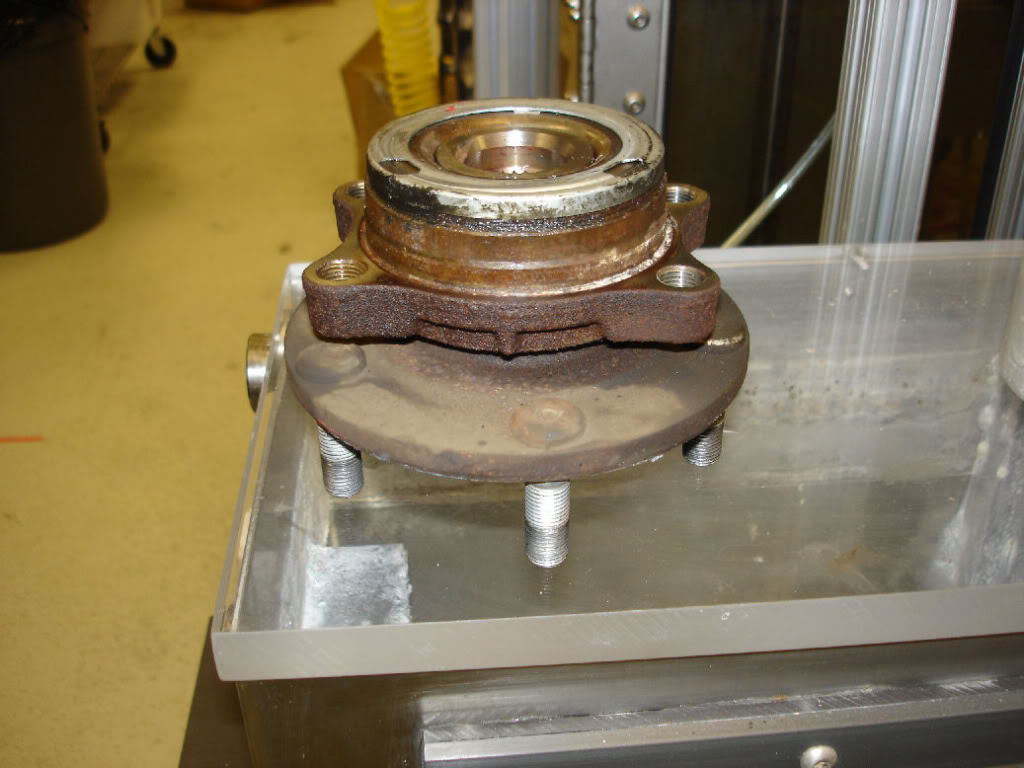
The hub slides into the bearing as shown with the "short" side being the side that faces the hub. Simply insert as far as you can by hand. Position on the press with the hub side down. Do not rest it on the lugs, but use a spacer to put the load on the center of the hub. You can see the aluminum block I used here
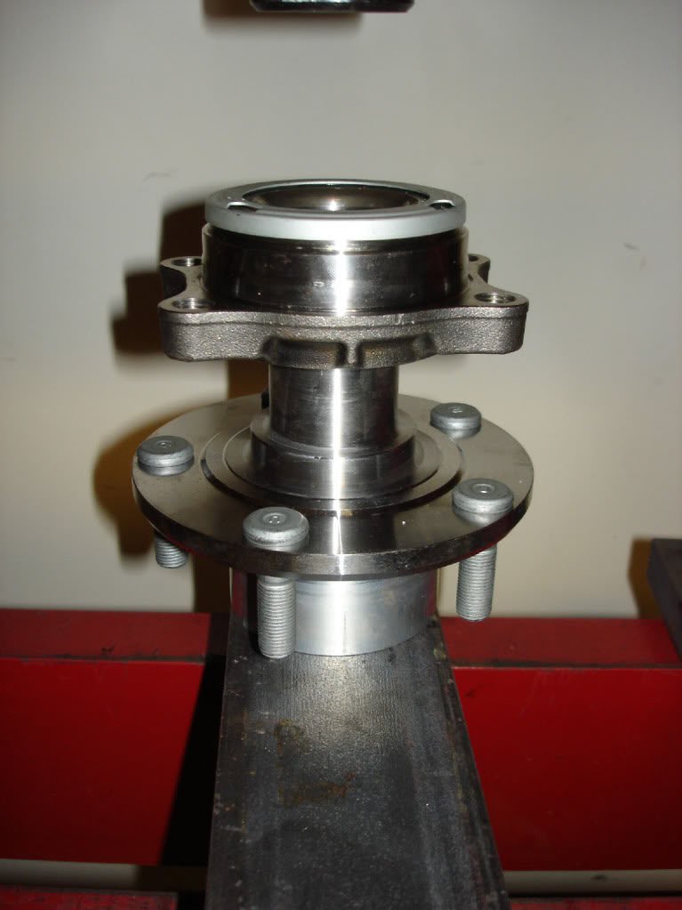
IMPORTANT STEP HERE. On the top of the bearing you do NOT want to press on the debris shield around the circumference of the bearing. you only want to press on the inner bearing race. You can see my spacer block here is only contacting the center. This is where you want to press down!
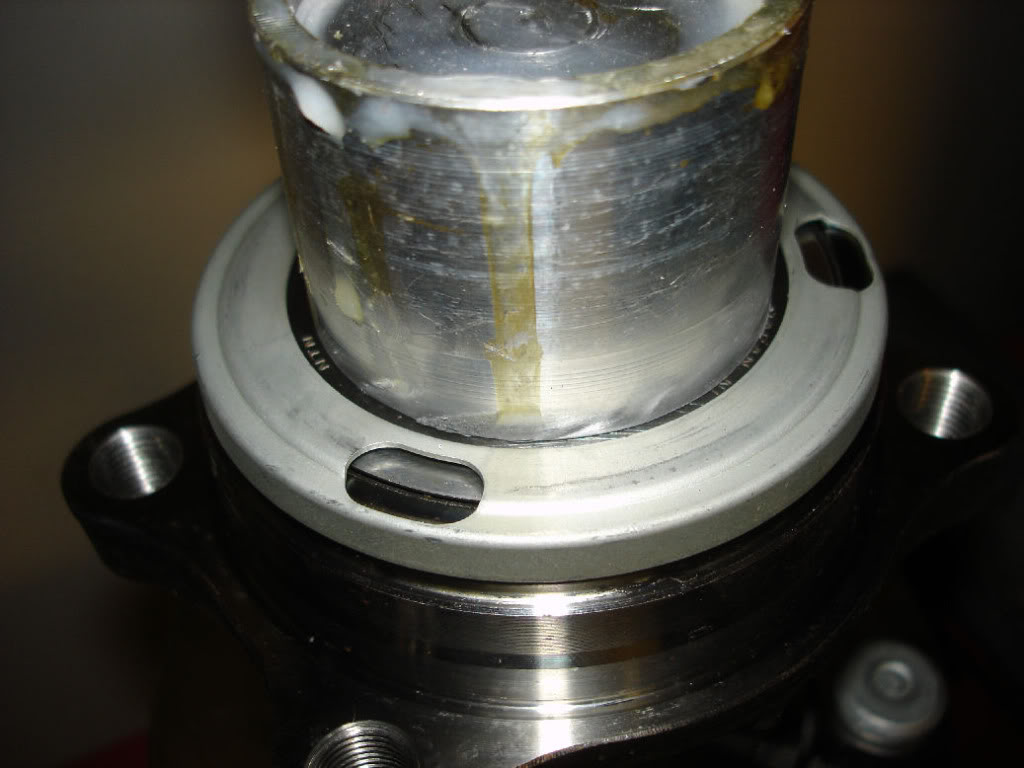
Here's a shot of the hub PARTIALLY pressed in. I wanted to show the correct orientation of the bearing and the hub and illustrate that there is a "lip" on the hub. You are going to press the bearing onto the hub and BOTTOM OUT this lip on the face of the bearing. FSM states final load to be 11,000 pounds of force (5.5 tons)
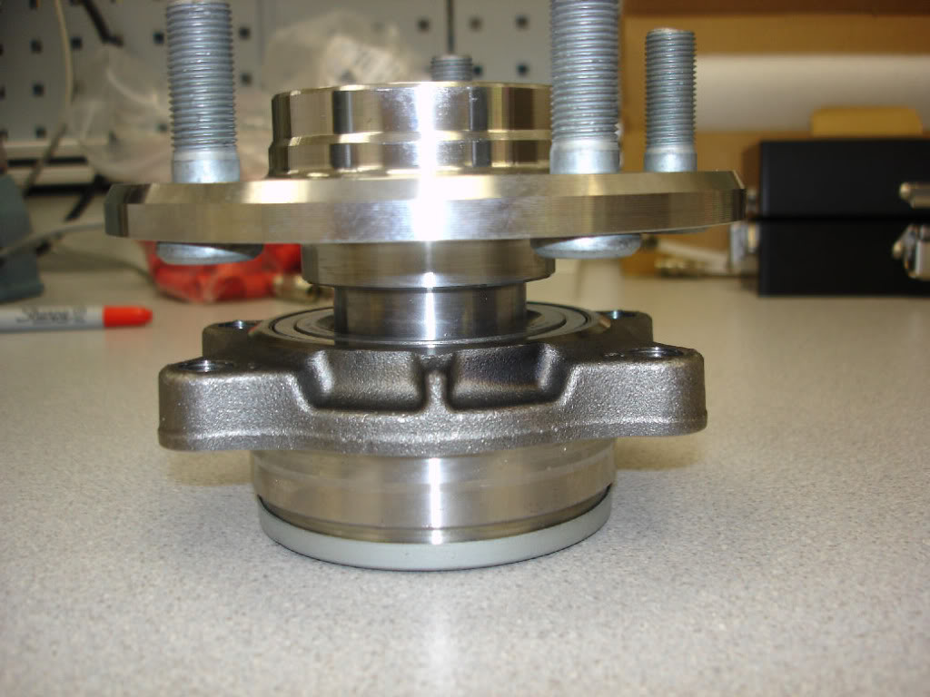
Again, just to clarify, the above picture is PARTIALLY pressed on. You can clearly see the part of the hub you want to bottom out on the bearing face
The final press. I used a different press with a gauge to press to the recommended 11,000 PSI per the FSM
[img] [/img]
The hub slides into the bearing as shown with the "short" side being the side that faces the hub. Simply insert as far as you can by hand. Position on the press with the hub side down. Do not rest it on the lugs, but use a spacer to put the load on the center of the hub. You can see the aluminum block I used here
IMPORTANT STEP HERE. On the top of the bearing you do NOT want to press on the debris shield around the circumference of the bearing. you only want to press on the inner bearing race. You can see my spacer block here is only contacting the center. This is where you want to press down!
Here's a shot of the hub PARTIALLY pressed in. I wanted to show the correct orientation of the bearing and the hub and illustrate that there is a "lip" on the hub. You are going to press the bearing onto the hub and BOTTOM OUT this lip on the face of the bearing. FSM states final load to be 11,000 pounds of force (5.5 tons)
Again, just to clarify, the above picture is PARTIALLY pressed on. You can clearly see the part of the hub you want to bottom out on the bearing face
The final press. I used a different press with a gauge to press to the recommended 11,000 PSI per the FSM
[img]
[/img]
Last edited by Mustang5L5; 08-08-2011 at 02:10 PM.
#3
07-31-2011, 09:11 PM
Disassembly
Park the car on a level, solid surface. Put trans in park, set the parking brake and chock the rear wheels if you'd wish. Don't jack up the front end on jackstands yet.
This next step assumes you have no impact gun to break the axle nut loose. If you have an impact, you can skip this, but the first thing i'd do is take the axle nut off.
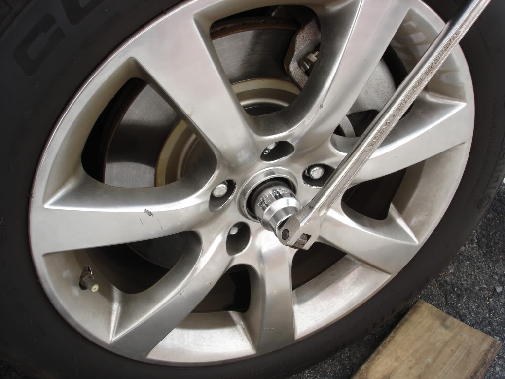
Break the lugs loose on the wheel you are going to work on. Jack up wheel, remove the tire and pop the center cap off. Remove the cotter pin from the cv axle. Put the wheel back on, and lower the car to the ground. Now stick the 32mm axle nut and breaker bar in where the center cap was. You can use a 6" extension, but i snapped mine. So be careful and maybe put a blanket on your fender if you are worried. But in any case, break the nut loose!
EDIT. If you have a helper and can't use the wheel method, have them stand on the brakes hard while you break the nut loose. This works if you have aftermarket wheels that the socket won't fit thru. Also, air impact gun will work here too.
Once you break it loose. Jack the front end and put both sides on jackstands and remove the wheel. I put my jackstands under the frame of the car where the lower control arms bolts to. Having both sides up will allow you to move the steering wheel and spin the wheels which will be helpful in the following steps.
If you had an impact gun, you would just put both sides up on jackstands...and zip the nut off.
This next step assumes you have no impact gun to break the axle nut loose. If you have an impact, you can skip this, but the first thing i'd do is take the axle nut off.
Break the lugs loose on the wheel you are going to work on. Jack up wheel, remove the tire and pop the center cap off. Remove the cotter pin from the cv axle. Put the wheel back on, and lower the car to the ground. Now stick the 32mm axle nut and breaker bar in where the center cap was. You can use a 6" extension, but i snapped mine. So be careful and maybe put a blanket on your fender if you are worried. But in any case, break the nut loose!
EDIT. If you have a helper and can't use the wheel method, have them stand on the brakes hard while you break the nut loose. This works if you have aftermarket wheels that the socket won't fit thru. Also, air impact gun will work here too.
Once you break it loose. Jack the front end and put both sides on jackstands and remove the wheel. I put my jackstands under the frame of the car where the lower control arms bolts to. Having both sides up will allow you to move the steering wheel and spin the wheels which will be helpful in the following steps.
If you had an impact gun, you would just put both sides up on jackstands...and zip the nut off.
Last edited by Mustang5L5; 08-01-2011 at 12:01 AM.
#4
07-31-2011, 09:15 PM
Next up, lets make some room. The spindle is gonna come out, so some of the smaller parts can be removed.
Optional: You don't need to remove the compression rod stop, but it does give you some room to free the steering link. Up to you, but it took all of 1 min to remove. You may choose to wait until rotor is removed if it will make it easier for you
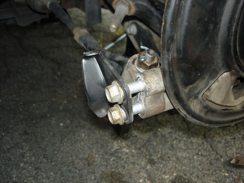
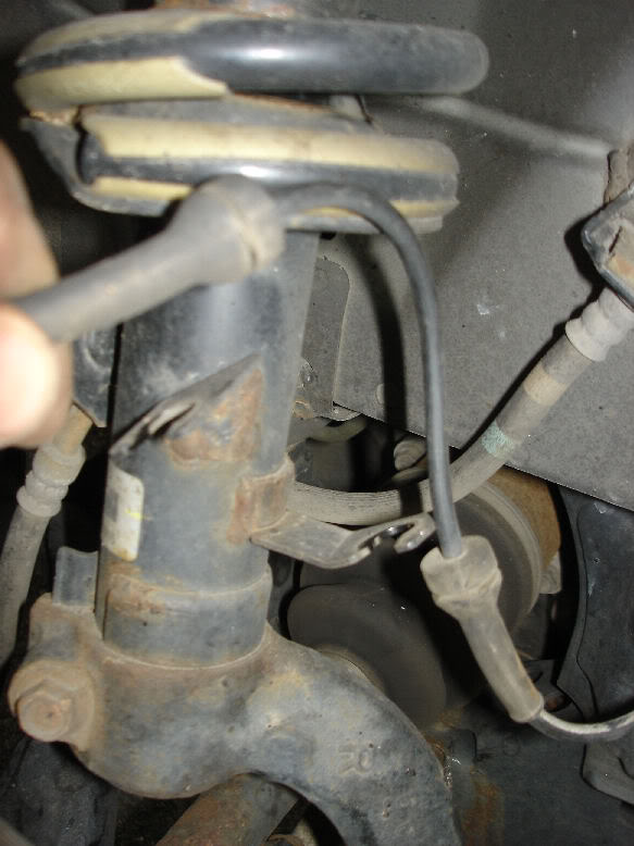
Remove the brake line support bracket from the spindle. (12mm bolts i believe)
Unbolt the ABS sensor and unclip from the spindle. Unclip it from the strut as well and move to a safe location
Optional: You don't need to remove the compression rod stop, but it does give you some room to free the steering link. Up to you, but it took all of 1 min to remove. You may choose to wait until rotor is removed if it will make it easier for you
Remove the brake line support bracket from the spindle. (12mm bolts i believe)
Unbolt the ABS sensor and unclip from the spindle. Unclip it from the strut as well and move to a safe location
Last edited by Mustang5L5; 07-31-2011 at 10:36 PM.
#5
07-31-2011, 09:19 PM
Next up, you are going to remove the brake caliper and rotor. Unbolt the caliper from the spindle using the 22mm socket. If you turn the steering wheel to full lock to the side you are working on, it makes accessing the bolts easier! With a breaker bar, you can crack them off easily.
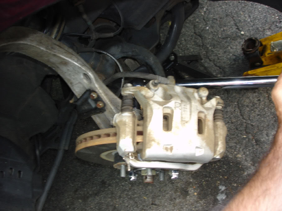
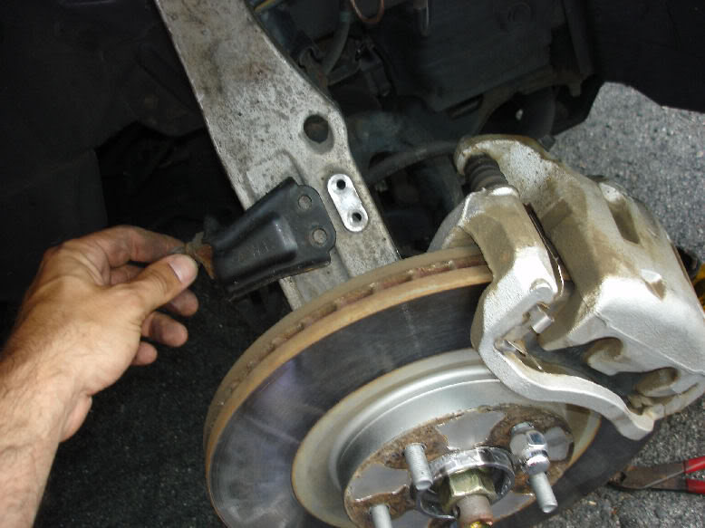
Remove the rotor. How easy this is depends on if you've done brakes recently or not and if you used anti-sieze. There are various brake DIY's showing how to remove seized rotors. Basically...whack the crap out of it with a 2x4 (so it doesn't damage rotor) or a rubber mallet. Eventially it will come off, and you will have this.
Support the caliper by hanging it. At first, we will hang it towards the front of the car, but when we unbolt the upper link, transfering it to the other side will give you room for what is next.
#6
07-31-2011, 09:24 PM
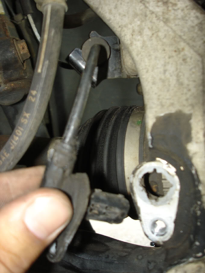
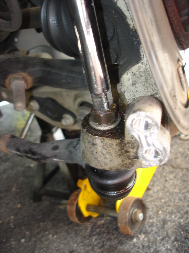
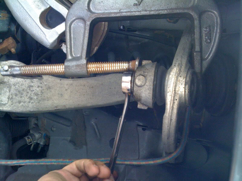
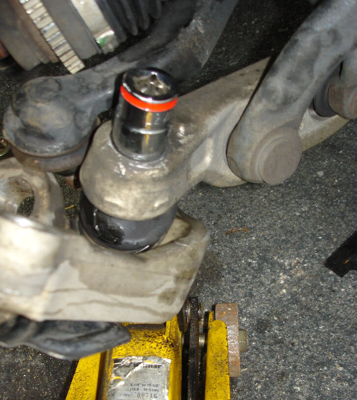
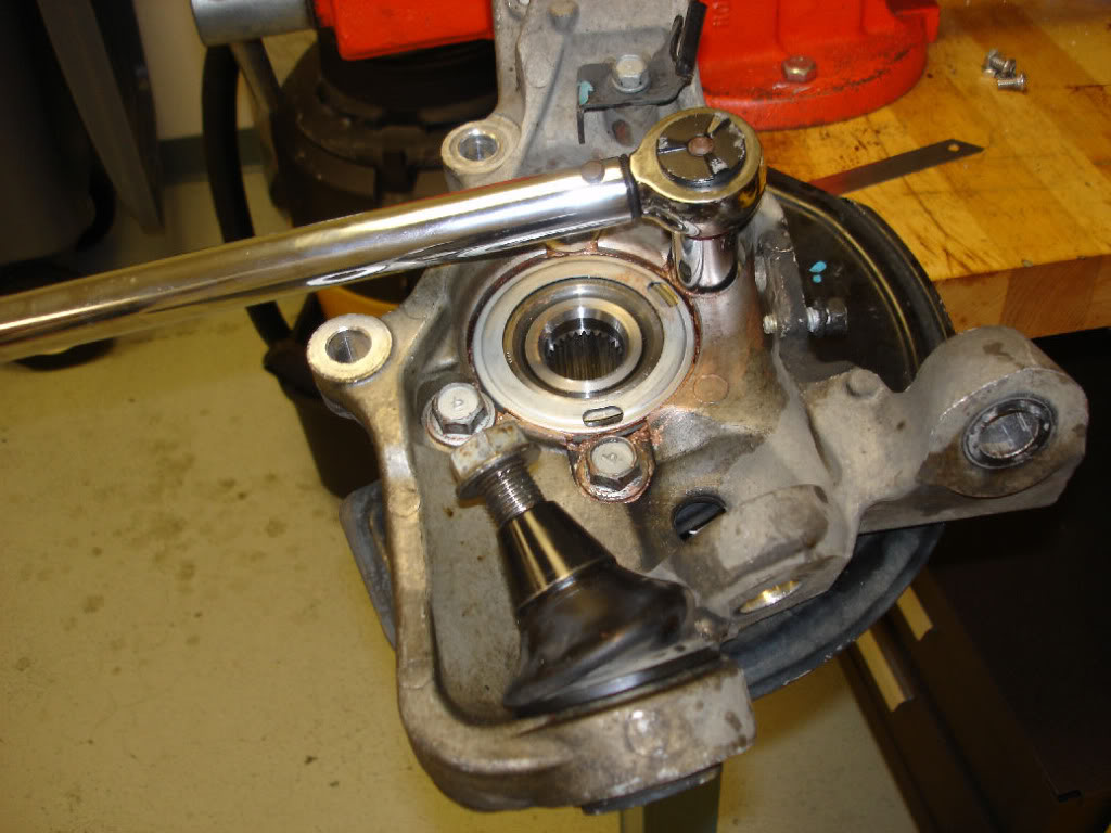
Remove the steering link first. First, remove the cotter pin. The nut here is either a 17mm or 19mm
Tip here, use a stiff wire brush to clean the threads up first, then remove the nut. It will make removal much easier!
I didn't need a separate to free it from the spindle. Once i had the nut removed, i placed the nut on the end of the shaft as shown, and put a 1/2 drive extension on top. A couple light taps with a hammer, and it popped loose!
If you try to remove it and fine the nut spins the entire balljoint, put a jack under the tie rod end and lift up slightly to put some pressure on it. DOn't do too much, just enough to stop it from spinning
You may need a separator to do this depending on how old your car is and mileage
Once free, i turned the steering wheel to pull the tie rod in to get it out of my way and give me more room.
Last edited by Mustang5L5; 08-16-2011 at 08:52 PM.
#7
07-31-2011, 09:27 PM
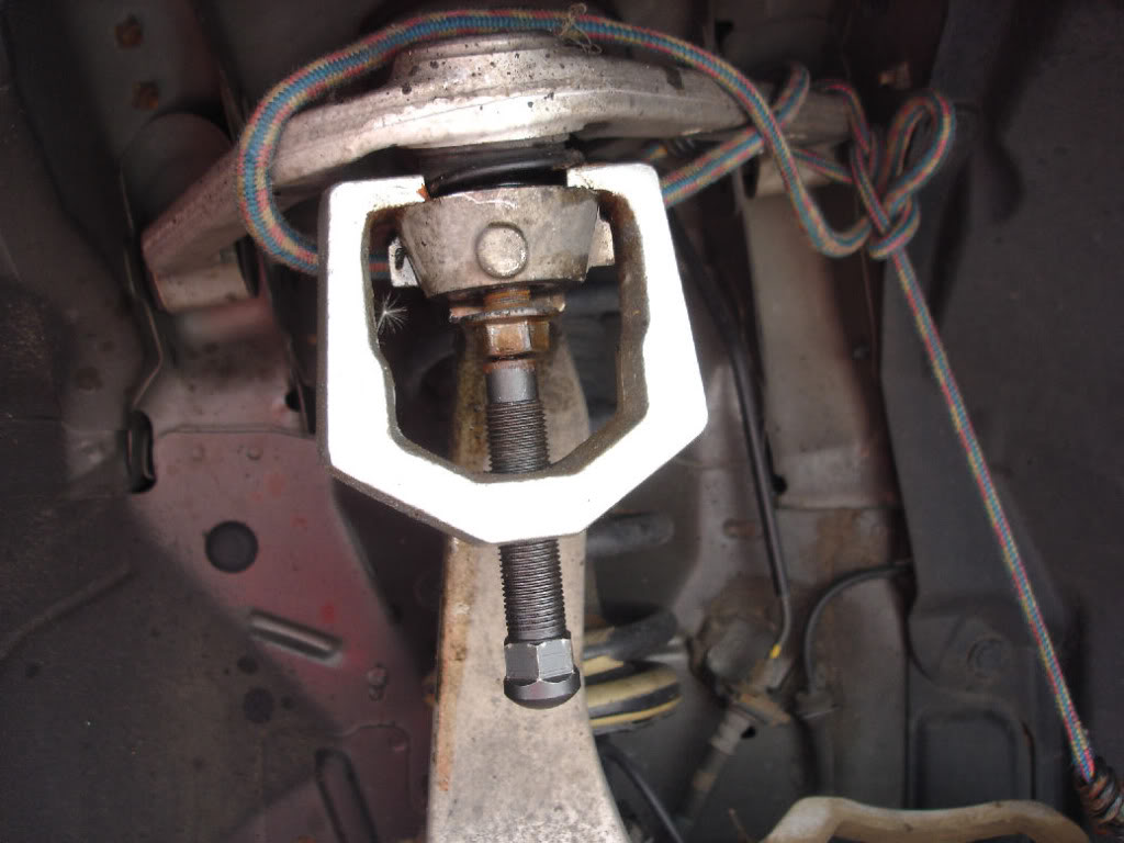
Next, we get to remove the upper control arm from the spindle. Remove the cotter pin. This was a 17mm socket i believe.
You may find that once the nut breaks loose, the entire ball joint spins. If this happens, use a clamp to put pressure on the spindle to the upper control arm and that should stop it from spinning.
Again, a stiff wire brush to the threads can make this easier. Also, if you have air tools, the nuts will prob zip right off.
If you can't separate the joint, a Pitman Arm Puller from Autozone will do the trick. I found mine was easy to separate. A good blow with a hammer on the stud (with nut threaded on end first) probably would have been all that was needed.
EDIT: 8/15/11 I was able to do my other side without a puller at all. I left the nut on the end and a few taps freed the upper arm from the knuckle
Last edited by Mustang5L5; 08-16-2011 at 08:51 PM.
Trending Topics
#8
07-31-2011, 09:31 PM
With the upper link undone, you'll find you can now pull the spindle outwards slightly. At this point, move the brake caliper over to the other side.
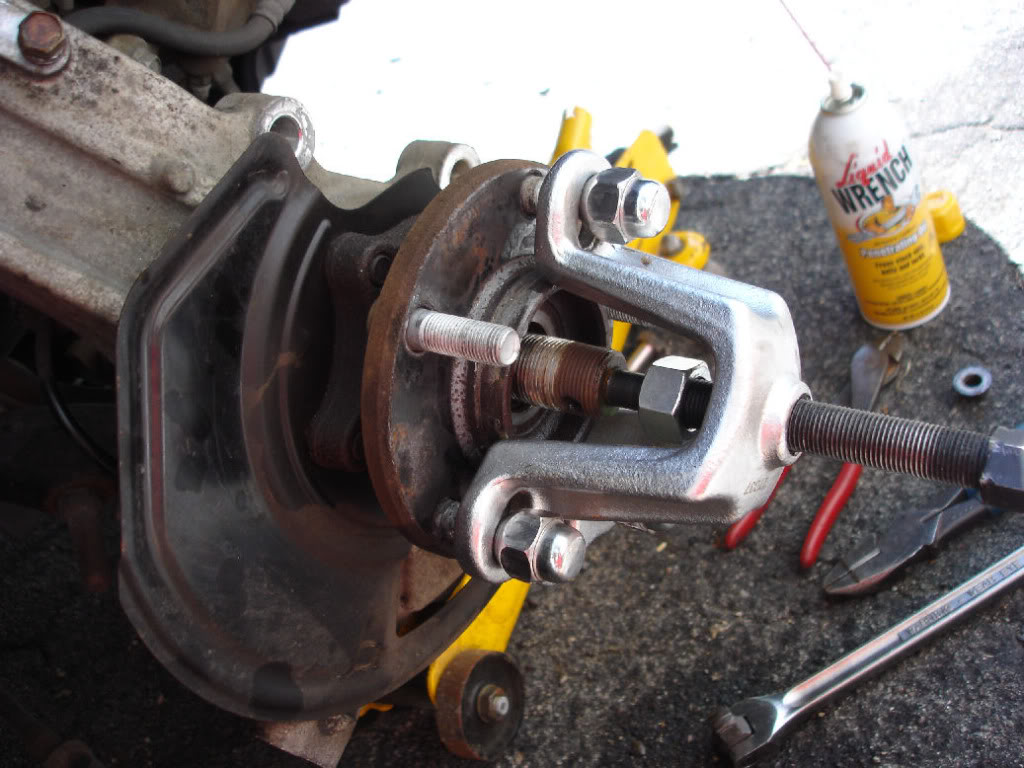
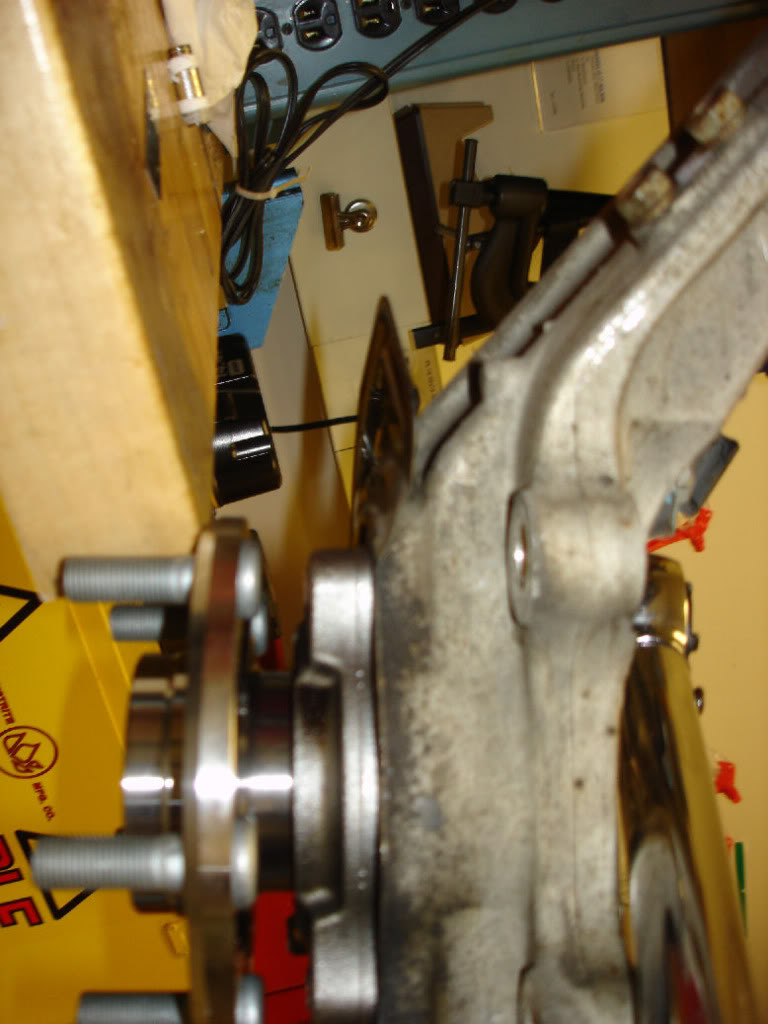
Now, we will push the axle out of the hub. I rented a FWD axle puller, but you can also use a 3-jaw puller here. It's simple as pie. Use 3 lugs to secure the puller to the hub. Don't tighten the lugs too much or you'll stick the puller to the hub. Just thread them on until the hub is bottomed out on the face of the hub. You'll be able to pull the axle out towards the front of the car.
This popped out so easy, that a few hits with a rubber mallet would probably have freed it. Be careful you don't mess up the threads. That's why the tool shown below is a better idea.
EDIT: 8/15/11 I was able to do the other side without a puller. I left the nut on the end and hit it with a 2x4 a few times and it moved. I then took it out by hand. Very easy
Last edited by Mustang5L5; 08-16-2011 at 08:53 PM.
#9
07-31-2011, 09:34 PM
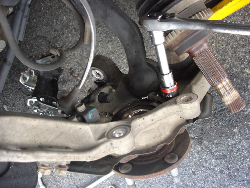
Now at this point, you have access to the 4 bearing bolts. They are 17mm. You can remove 3 of them completely at this point, but one is positioned behind the compression rod and cannot be completely removed. You might have a tough time getting at the bolt. If you are planning on removing the spindle like i did here, you can just leave it and unbolt all 4 (or the 1) once the spindle is removed, otherwise if you are feeling brave, or have a low-mileage or southern car, you can loosen the bottom bolt as much as possible, then reassembly the upper control arm link and bang away with a slide hammer....choice is up to you here
 \
\
You can see the issue with the bottom bolt here hitting the compression rod.
\You can see the issue with the bottom bolt here hitting the compression rod.
#10
07-31-2011, 09:39 PM
If you are continuing on to remove the spindle, here we go.
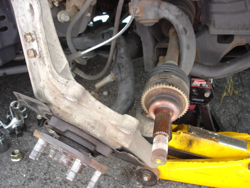
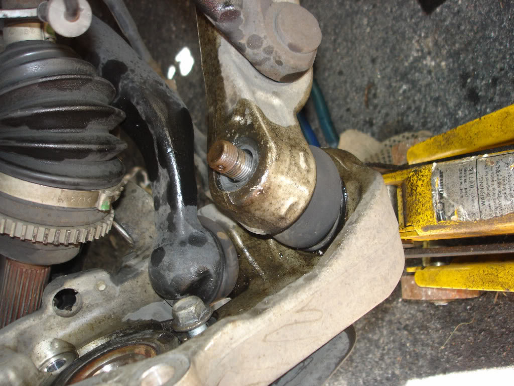
Next up, we need to remove the Compression rod and lower control arm. I chose to undo the lower control arm first. You'll need a 22mm socket here. Remove the cotter pin and unbolt. If you find the ball-joint is spinning, position a jack under the ball-joint and lift up slightly. It should put enough pressure to seat the joint and allow you to remove the nut. Again, wire-brushing and penetrating lubricant come in handy here
Once removed, the spindle separated easily from the lower control arm. No need for any separator.
You can see the jack positioned under the ball joint here. (this photo is just to illustrate as I already had the compression rod and lower arm off...but wanted to show the "jack trick")
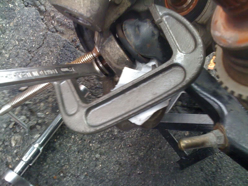
Finally, remove the cotter pin and remove the nut on the compression rod. Wire-brush and penetrating fluid will come in handy here again! if you find the balljoint is spinning, use a c-clamp to clamp between the compression rod and spindle. Then remove the nut with a wrench as you might not be able to get a socket in. Light pressure will seat the joint and allow you to remove the nut.
Next up, we need to remove the Compression rod and lower control arm. I chose to undo the lower control arm first. You'll need a 22mm socket here. Remove the cotter pin and unbolt. If you find the ball-joint is spinning, position a jack under the ball-joint and lift up slightly. It should put enough pressure to seat the joint and allow you to remove the nut. Again, wire-brushing and penetrating lubricant come in handy here
Once removed, the spindle separated easily from the lower control arm. No need for any separator.
You can see the jack positioned under the ball joint here. (this photo is just to illustrate as I already had the compression rod and lower arm off...but wanted to show the "jack trick")
Finally, remove the cotter pin and remove the nut on the compression rod. Wire-brush and penetrating fluid will come in handy here again! if you find the balljoint is spinning, use a c-clamp to clamp between the compression rod and spindle. Then remove the nut with a wrench as you might not be able to get a socket in. Light pressure will seat the joint and allow you to remove the nut.
Last edited by Mustang5L5; 08-16-2011 at 08:53 PM.
#11
07-31-2011, 09:42 PM
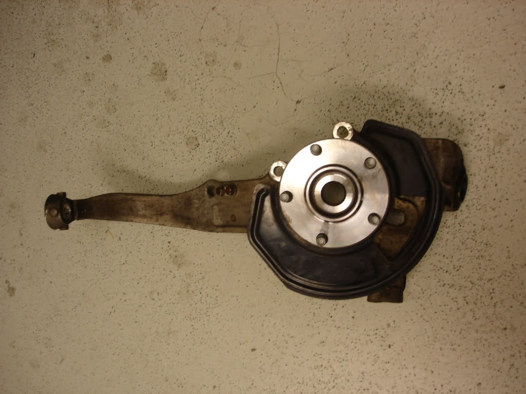
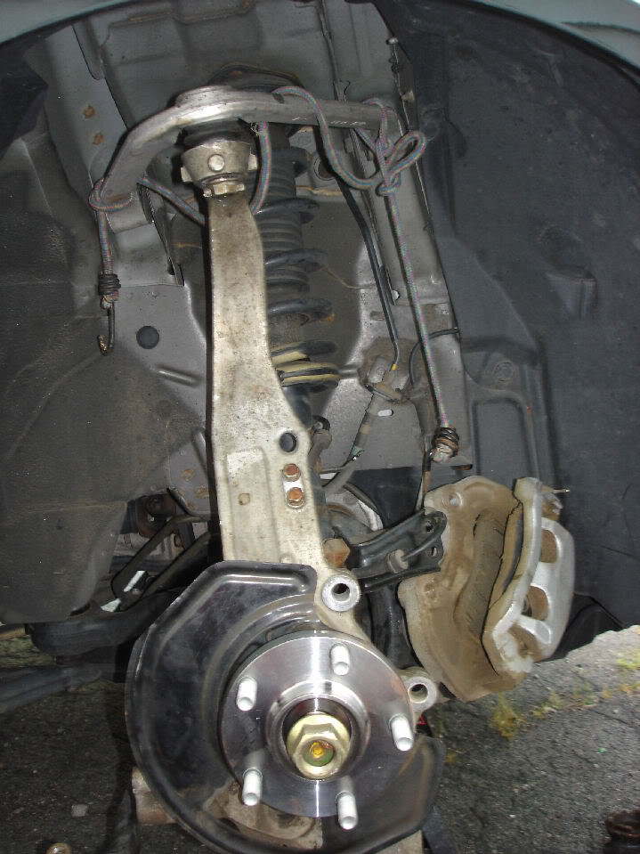
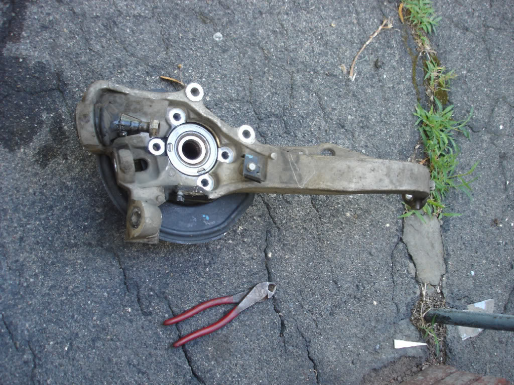
With the compression rod undone, pull the spindle out. This is what you should be left with!
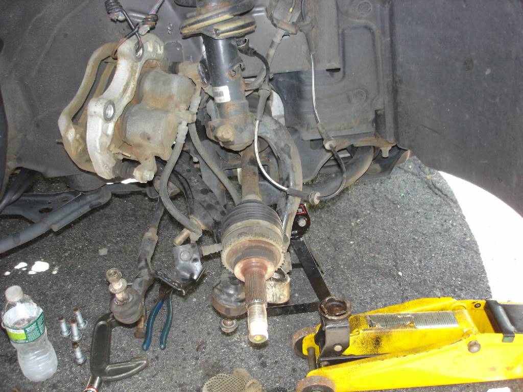
Remove the bearing bolts now if you haven't done so. A little brake cleaner will help clean up all the penetrating fluids you prob sprayed everywhere and keep the spindle somewhat clean for the next step.
Remove the bearing bolts now if you haven't done so. A little brake cleaner will help clean up all the penetrating fluids you prob sprayed everywhere and keep the spindle somewhat clean for the next step.
Last edited by Mustang5L5; 08-02-2011 at 11:05 PM.
#12
07-31-2011, 09:46 PM
EDIT: 4/7/14 THIS STEP CAN BE PERFORMED WITHOUT A PRESS! SCROLL TO BOTTOM OF THIS POST FOR THAT METHOD
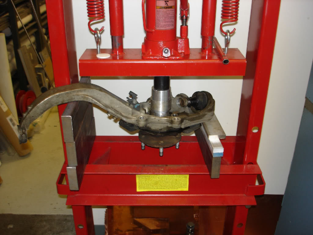
Hopefully you have access to a press, or know someone with a press, because you'll need it. This is how i set up the press. I used spacers under the upper end and lower end just short of the dust sheild. Don't rest it on the shield, you will bend it.
EDIT: 4/7/14 was able to remove without a press...scroll to bottom for method
The spindle is forged aluminum...which is very strong. But do NOT use heat on it or you will weaken it. Penetrating fluid only!
You can see here where i pressed on the bearing
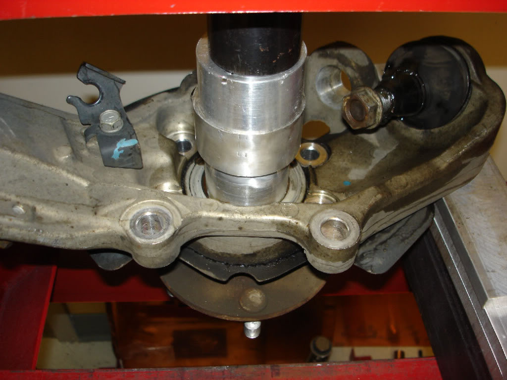
Be carefull as i needed some force. When the bearing finally gave, it POPPED out and the entire assembly fell to the floor. So be ready!
EDIT 4/7/14. Had a 3rd bearing fail. This time i was able to remove without a press. I took two blocks of wood and put the knucle on it with the hub bearing facing down. I backed the 4 bolts out about 1/4" away. I then took a rod of aluminum (to not damage the bolt heads) and a hammer and proceeded to hit the bolt heads around in a cross pattern. Amazingly, the bearing moved, and I was able to hit it out pretty easily this way. Took me all of 2 mins to hit it out and no damage to bolt heads.
edit 3/8/16 To date, I've done 3 bearing installs since without using the press in this step. I simply prop the kuckle on some boards of wood, back the bearing bolts out a tad, and then strike them (with an aluminum rod to not damage the bolts) in a criss cross pattern and out they come. No press needed here.
Hopefully you have access to a press, or know someone with a press, because you'll need it. This is how i set up the press. I used spacers under the upper end and lower end just short of the dust sheild. Don't rest it on the shield, you will bend it.
EDIT: 4/7/14 was able to remove without a press...scroll to bottom for method
The spindle is forged aluminum...which is very strong. But do NOT use heat on it or you will weaken it. Penetrating fluid only!
You can see here where i pressed on the bearing
Be carefull as i needed some force. When the bearing finally gave, it POPPED out and the entire assembly fell to the floor. So be ready!
EDIT 4/7/14. Had a 3rd bearing fail. This time i was able to remove without a press. I took two blocks of wood and put the knucle on it with the hub bearing facing down. I backed the 4 bolts out about 1/4" away. I then took a rod of aluminum (to not damage the bolt heads) and a hammer and proceeded to hit the bolt heads around in a cross pattern. Amazingly, the bearing moved, and I was able to hit it out pretty easily this way. Took me all of 2 mins to hit it out and no damage to bolt heads.
edit 3/8/16 To date, I've done 3 bearing installs since without using the press in this step. I simply prop the kuckle on some boards of wood, back the bearing bolts out a tad, and then strike them (with an aluminum rod to not damage the bolts) in a criss cross pattern and out they come. No press needed here.
Last edited by Mustang5L5; 03-08-2016 at 09:06 AM.
#13
07-31-2011, 09:54 PM
The old bearing.....all sorts of grinding coming from this.
At this point, if you are reusing your hub, you gotta press or pull it out. There are various methods you can use, but since I haven't don't it yet, I can't elaborate. Pulling the hub destroys the bearing as it pulls the front race out, obviously....who cares? But getting the race off might be tricky. You basically have to dremel a slot and break the race open a bit to slide it off. Might be a PITA and something you don't want to do while your car is apart and you gotta go to work the next day. Needless to say, I highly recommend buying a bearing and hub and pre-pressing them ahead of time. Then, when you do thisnjob, you are ready to go. Later on, at your own leisure, you can work on pulling the hub and either save it for the future (or other side) or sell it on EBay. These hubs (and bearings) work only in the front. The rear bearings/hubs look similar, but are slightly different. Different part numbers out back (same as 2wd sedan/coupe rears)
EDIT: 4/11/2014. Was able to press out old hub. See post #57 on how I did this.
Keep in mind, a bad hub could be the reason why the bearing failed. When in doubt...buy a new hub.
With the spindle empty, take some time to clean out the hole where the bearing sits. I used a wire brush attachment on a cordless drill, but you can use a hand wire brush as well. I also chose to apply copper high-temp anti-seize here. Hate to say it, but you may need to do this job again at some point. Hopefully, with any luck, the anti-seize allows you to be able to remove the bearing easily with a slide hammer rather than having to press it out. Worth a shot.
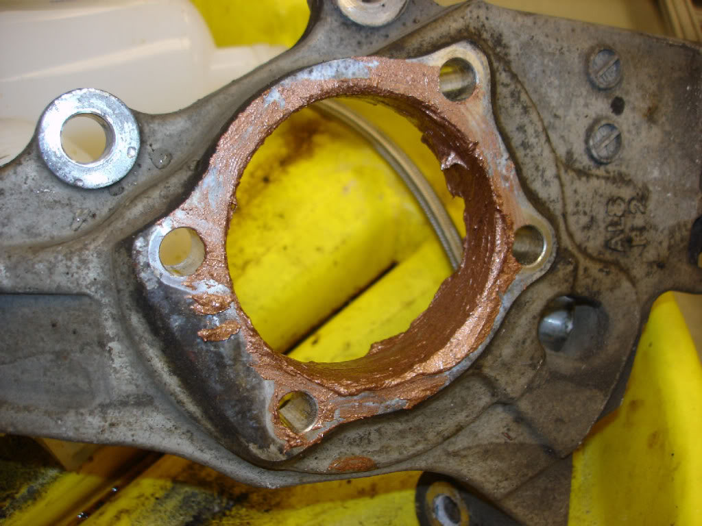
Take note of the dust shield. It fits on TWO ways, but you want the shield to be positioned away from the rotor and in towards the spindle. So pay attention here!
At this point, if you are reusing your hub, you gotta press or pull it out. There are various methods you can use, but since I haven't don't it yet, I can't elaborate. Pulling the hub destroys the bearing as it pulls the front race out, obviously....who cares? But getting the race off might be tricky. You basically have to dremel a slot and break the race open a bit to slide it off. Might be a PITA and something you don't want to do while your car is apart and you gotta go to work the next day. Needless to say, I highly recommend buying a bearing and hub and pre-pressing them ahead of time. Then, when you do thisnjob, you are ready to go. Later on, at your own leisure, you can work on pulling the hub and either save it for the future (or other side) or sell it on EBay. These hubs (and bearings) work only in the front. The rear bearings/hubs look similar, but are slightly different. Different part numbers out back (same as 2wd sedan/coupe rears)
EDIT: 4/11/2014. Was able to press out old hub. See post #57 on how I did this.
Keep in mind, a bad hub could be the reason why the bearing failed. When in doubt...buy a new hub.
With the spindle empty, take some time to clean out the hole where the bearing sits. I used a wire brush attachment on a cordless drill, but you can use a hand wire brush as well. I also chose to apply copper high-temp anti-seize here. Hate to say it, but you may need to do this job again at some point. Hopefully, with any luck, the anti-seize allows you to be able to remove the bearing easily with a slide hammer rather than having to press it out. Worth a shot.
Take note of the dust shield. It fits on TWO ways, but you want the shield to be positioned away from the rotor and in towards the spindle. So pay attention here!
Last edited by Mustang5L5; 04-11-2014 at 10:44 AM.
#14
07-31-2011, 09:57 PM
Bolt the bearing on. It only fits one way, so don't be concerned with which end is up. If you can get the 4 bolts in, its the right way.
With mine, i could only get the bearing in 1/2way before it stopped. I threaded the 4 bolts in and tightened them evenly in an X-pattern to draw in the bearing. It slid in easy. I could have used the press, but it wasn't necessary.
I used a vice to hold the spindle. Torque the 4 bolts to 58-72 ft-lbs (per the FSM)
Again, double-check the dust sheild. You don't want to pull this all apart again to flip it. You want it to position it away from the brake rotor and up against the spindle.
Wipe up any excess anti-seize when done.
Last edited by Mustang5L5; 08-01-2011 at 08:55 AM.