Help!! Adding oem paddle shifter to G35 coupe
#1
 06-19-2011, 01:42 AM


Help!! Adding oem paddle shifter to G35 coupe
Hi everyone, I’m trying to add OEM peddle shifters to G35 coupe.
Since I watched a video and knew it is possible.
I checked both transmission diagrams and found that there are no differences.
I tried to wiring as below diagram, but it doesn’t work.
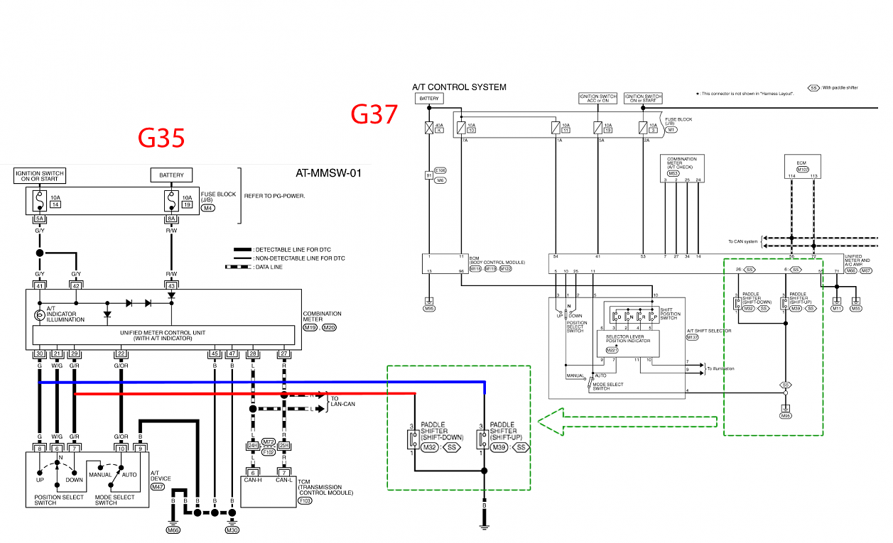
I think I need to add some modules and make it when pebble Shifter “UP”(Pin: 7) (or Down (Pin: 8)), and block “N”(Pin: 6) electricity running.

Does anyone have any ideas for the module what should I use for, or different ideas for the method?
Help please~.
Since I watched a video and knew it is possible.
I checked both transmission diagrams and found that there are no differences.
I tried to wiring as below diagram, but it doesn’t work.
I think I need to add some modules and make it when pebble Shifter “UP”(Pin: 7) (or Down (Pin: 8)), and block “N”(Pin: 6) electricity running.
Does anyone have any ideas for the module what should I use for, or different ideas for the method?
Help please~.
#5
06-19-2011, 03:04 AM
I know it works bell has it, but those paddles are ugly for me.
Beside, by my analysis in the below picture (the harness will be given from Works Bell), if you know what is going on the black box, you can it by yourself.
So, does everyone have any ideas?
Beside, by my analysis in the below picture (the harness will be given from Works Bell), if you know what is going on the black box, you can it by yourself.
So, does everyone have any ideas?
Last edited by Till; 06-19-2011 at 03:13 AM.
#6
06-19-2011, 03:11 AM
Or the other after market paddle from Nengun, they have more simplified harness for it.
http://www.nengun.com/night-pager/column-shifter
the algorithm is the same as Works Bell using.
As you can see from the picture, they took from 4 wires from OEM wire to the plug, and then seem like just simply use 4 wires plug connect to 2 wires plug.
Since the plug is kind of big, I dont know what kind of wiring is inside of it.
#7
06-19-2011, 08:47 AM

You will most likely have to break the "auto" signal too. You should be able to do this with relays.
When you press the down shift button have it break the auto signal, have it break the N signal, and have it apply ground to the down input.
When you press the up shift button have it break the auto signal, have it break the N signal, and have it apply ground to the up input.
You can use two small DPDT relays - one for up, one for down.
Take the Auto signal and run in through the NC#1 contact of down relay and through NC#1 contact of up relay. This will take care of breaking this signal when either button is pushed.
Do the same thing with the N signal by using NC#2 contact on each relay
Lastly, wire the switch outputs to the respective coil (with diodes across each coil) and also wire the switch output to the respective up and down inputs.
The following users liked this post:
Till (06-20-2011)
Trending Topics
#9
06-20-2011, 11:11 PM
I did wiring as your described, however, it didnt work too. The picture is showing just up side wiring diagram.
Since I am not very understand the relay, Should I connect some on "COM"??
Help!!
Since I am not very understand the relay, Should I connect some on "COM"??
Help!!
You will most likely have to break the "auto" signal too. You should be able to do this with relays.
When you press the down shift button have it break the auto signal, have it break the N signal, and have it apply ground to the down input.
When you press the up shift button have it break the auto signal, have it break the N signal, and have it apply ground to the up input.
You can use two small DPDT relays - one for up, one for down.
Take the Auto signal and run in through the NC#1 contact of down relay and through NC#1 contact of up relay. This will take care of breaking this signal when either button is pushed.
Do the same thing with the N signal by using NC#2 contact on each relay
Lastly, wire the switch outputs to the respective coil (with diodes across each coil) and also wire the switch output to the respective up and down inputs.
When you press the down shift button have it break the auto signal, have it break the N signal, and have it apply ground to the down input.
When you press the up shift button have it break the auto signal, have it break the N signal, and have it apply ground to the up input.
You can use two small DPDT relays - one for up, one for down.
Take the Auto signal and run in through the NC#1 contact of down relay and through NC#1 contact of up relay. This will take care of breaking this signal when either button is pushed.
Do the same thing with the N signal by using NC#2 contact on each relay
Lastly, wire the switch outputs to the respective coil (with diodes across each coil) and also wire the switch output to the respective up and down inputs.
#10
06-21-2011, 07:34 AM
Yes, you have to hook up the com contact. You must CUT each wire and run it THROUGH the relay - in on NC and out on COM (or vice versa). The relay must interrupt the signals.
Also, the coil wiring is wrong. One side of the coil has to go to 12vdc and the other to your switch.
Your switch output needs to go directly to the switch input AND to one side of the coil.
Also, the coil wiring is wrong. One side of the coil has to go to 12vdc and the other to your switch.
Your switch output needs to go directly to the switch input AND to one side of the coil.

#13
10-11-2011, 11:21 AM

I know this is an older thread but can you post the model DPDT relays you used and the final wiring?
Also do you have to put it in manumatic to make it work or does it work like the newer cars where you can pull them anytime and it will go into manumatic?
thanks so much
evo
Also do you have to put it in manumatic to make it work or does it work like the newer cars where you can pull them anytime and it will go into manumatic?
thanks so much
evo
Last edited by evo626; 10-11-2011 at 11:32 AM.
#14
10-15-2012, 09:27 AM
http://minkara.carview.co.jp/en/user.../blog/5612310/
To those all inquired this, please check website attached.
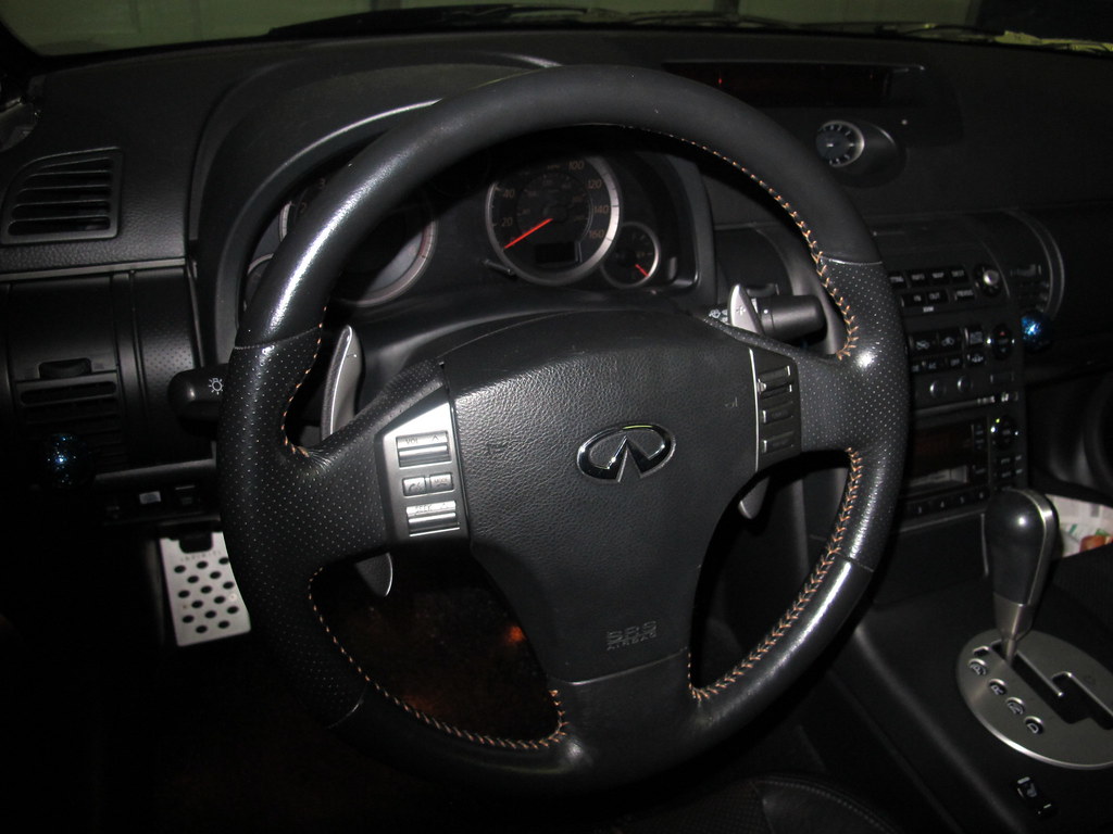
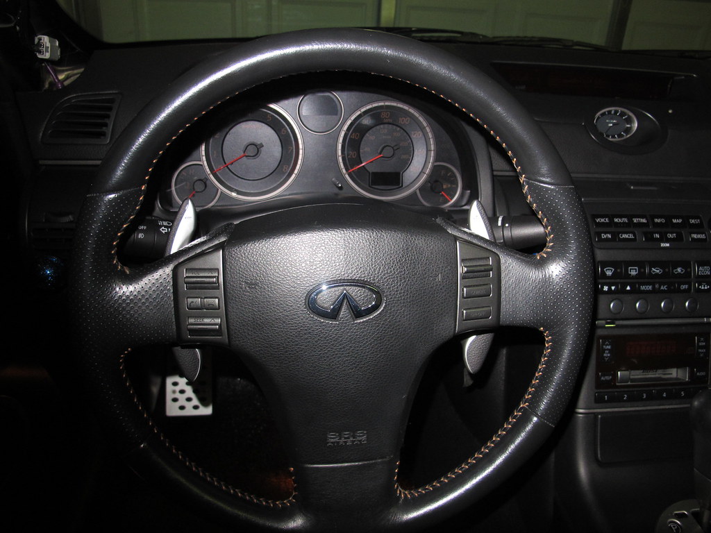
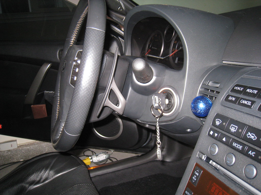
The peddle shifter musts hit the back of steering wheel. I tired my best to cut and sharp it. However, it couldn't work, still hitting. Eventually I removed it. So I believe this is no worth to try.
Looking for another option.
To those all inquired this, please check website attached.
The peddle shifter musts hit the back of steering wheel. I tired my best to cut and sharp it. However, it couldn't work, still hitting. Eventually I removed it. So I believe this is no worth to try.
Looking for another option.