Light mods
#1
 06-17-2009, 04:41 AM


Light mods
Just want to give you guys an update. (since, obviously I can't show you in person anymore)
I have opened up my rear tail lights (like I said I always wanted to )
)
I split my passenger side lens, so I have to procure another one, somehow.
I'm also working on my bumper marker lights.
I am installing LED's into the outer circle reflector area. 8 in there and 2 will go on the side for turn signal indications.
On my side markers. These are the new style JDM lights with the "bump". The design is 30 amber leds per side and 10 white per side. I'm waiting on some parts to come in to finish that project as well as the tail lights.
Here is a picture of the tails. With and without the cover, wish I could find clear covers, that would be sick!

Here is the LED turn signal, pretty much complete. Next I'll mount it and trim up the housing so it will fit and I will hook it up to the car so we can see how it looks compared to the brake and normal turn signal
Ckt Board Front

Ckt Board Rear

Powered at 12v (power supply is only putting out 11v when hooked up )
)

In the new Signal Spot

The whole housing at 1/100 5.6 (just like the rest of the pictures)

The whole housing at 1/60 3.2 (more like what your eyes would see)

Glued into place (Silicone in the middle and Hot Glue on the edge)

I had to trim this in order for the board to fit. (Didn't feel like pulling out the rotary, so I used wire cutters )

Here you can see how close the fit is.

Parking Light

Parking + Blinker

Brake + Blinker

Edit:
Done with the sides, just have to wire them into the car
Here is the ckt board. 40 leds in total so as you'll see in the next pic, it needs more room.

As you can see I had to dremel down the backing in order to get the leds to fit into the case.

Parking light

Signal light

Parking + Signal

I could make these about twice as bright. I tested it with higher voltages, but I don't want to risk overloading them. When the car is running the voltage being supplied fluctuates. At WOT they will get over 14+ volts. Regular running around 13 and when the engine isn't running 12v.
The pictures are all running on a 12v power supply in the house. I will proceed to wiring them up tomorrow, as long as it isn't raining
01/13/2010
Finally did the reverse lamps
I cut these open a little bit differently. I cut them the way I was talking about a while ago. This way was tons easier than going sideways. Plus this has the added benefit of not messing up the clear lens either
Unfortunately it means you wont cut it perfectly and will/might hit some of the reflector. Easy fix though. Just paint the clear lens on the inside near the edges. This will help blend it all together.
See where the edge of the red plastic is serrated? This is where you want to cut. It seems to be where the parts were melted together.


Inner housing. This is the area that was painted.

This is the lens. I ended up taping the inside with masking tape and leaving the edges untaped. I also taped the front and sides, but not the back of the sides. After that I painted it black. (Sorry, I didn't take pictures of that. I wanted to get this buttoned up, because it was raining a little bit)

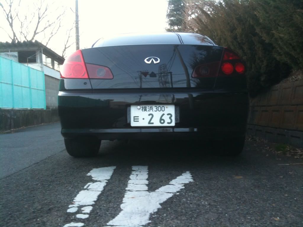
How they look at night. The driver side outer light is a stock JDM light.

Daytime pic taken with my iPhone, sorry
Again driver side housing/lens is a stock JDM unit.
I have opened up my rear tail lights (like I said I always wanted to
)I split my passenger side lens, so I have to procure another one, somehow.
I'm also working on my bumper marker lights.
I am installing LED's into the outer circle reflector area. 8 in there and 2 will go on the side for turn signal indications.
On my side markers. These are the new style JDM lights with the "bump". The design is 30 amber leds per side and 10 white per side. I'm waiting on some parts to come in to finish that project as well as the tail lights.
Here is a picture of the tails. With and without the cover, wish I could find clear covers, that would be sick!
Here is the LED turn signal, pretty much complete. Next I'll mount it and trim up the housing so it will fit and I will hook it up to the car so we can see how it looks compared to the brake and normal turn signal
Ckt Board Front
Ckt Board Rear
Powered at 12v (power supply is only putting out 11v when hooked up
)In the new Signal Spot
The whole housing at 1/100 5.6 (just like the rest of the pictures)
The whole housing at 1/60 3.2 (more like what your eyes would see)
Glued into place (Silicone in the middle and Hot Glue on the edge)
I had to trim this in order for the board to fit. (Didn't feel like pulling out the rotary, so I used wire cutters
)Here you can see how close the fit is.
Parking Light
Parking + Blinker
Brake + Blinker
Edit:
Done with the sides, just have to wire them into the car
Here is the ckt board. 40 leds in total so as you'll see in the next pic, it needs more room.
As you can see I had to dremel down the backing in order to get the leds to fit into the case.
Parking light
Signal light
Parking + Signal
I could make these about twice as bright. I tested it with higher voltages, but I don't want to risk overloading them. When the car is running the voltage being supplied fluctuates. At WOT they will get over 14+ volts. Regular running around 13 and when the engine isn't running 12v.
The pictures are all running on a 12v power supply in the house. I will proceed to wiring them up tomorrow, as long as it isn't raining
01/13/2010
Finally did the reverse lamps
I cut these open a little bit differently. I cut them the way I was talking about a while ago. This way was tons easier than going sideways. Plus this has the added benefit of not messing up the clear lens either
Unfortunately it means you wont cut it perfectly and will/might hit some of the reflector. Easy fix though. Just paint the clear lens on the inside near the edges. This will help blend it all together.
See where the edge of the red plastic is serrated? This is where you want to cut. It seems to be where the parts were melted together.
Inner housing. This is the area that was painted.
This is the lens. I ended up taping the inside with masking tape and leaving the edges untaped. I also taped the front and sides, but not the back of the sides. After that I painted it black. (Sorry, I didn't take pictures of that. I wanted to get this buttoned up, because it was raining a little bit)
How they look at night. The driver side outer light is a stock JDM light.
Daytime pic taken with my iPhone, sorry
Again driver side housing/lens is a stock JDM unit.
Last edited by psedog; 01-13-2010 at 07:52 AM. Reason: Reverse light update :D
#2
06-17-2009, 11:38 AM

Registered User
Join Date: Apr 2008
Location: san diego
Posts: 700
Likes: 0
Received 0 Likes
on
0 Posts
#3
06-17-2009, 11:58 AM


#6
06-17-2009, 11:47 PM
#7
06-17-2009, 11:51 PM

Trending Topics
#10
06-21-2009, 01:53 PM

#13
06-22-2009, 05:31 AM
It rained, but I installed them anyway
<object width="480" height="385"><param name="movie" value="http://www.youtube.com/v/M6e5MfswGyE&hl=en&fs=1&color1=0x3a3a3a&color2=0x99 9999"></param><param name="allowFullScreen" value="true"></param><param name="allowscriptaccess" value="always"></param><embed src="http://www.youtube.com/v/M6e5MfswGyE&hl=en&fs=1&color1=0x3a3a3a&color2=0x99 9999" type="application/x-shockwave-flash" allowscriptaccess="always" allowfullscreen="true" width="480" height="385"></embed></object>
<object width="480" height="385"><param name="movie" value="http://www.youtube.com/v/M6e5MfswGyE&hl=en&fs=1&color1=0x3a3a3a&color2=0x99 9999"></param><param name="allowFullScreen" value="true"></param><param name="allowscriptaccess" value="always"></param><embed src="http://www.youtube.com/v/M6e5MfswGyE&hl=en&fs=1&color1=0x3a3a3a&color2=0x99 9999" type="application/x-shockwave-flash" allowscriptaccess="always" allowfullscreen="true" width="480" height="385"></embed></object>
#14
06-22-2009, 04:16 PM
Registered User
Join Date: Apr 2008
Location: san diego
Posts: 700
Likes: 0
Received 0 Likes
on
0 Posts


