How To Wire in AUTO FOLD feature for your JDM Folding Mirrors
#1
 06-01-2012, 06:04 PM

How To Wire in AUTO FOLD feature for your JDM Folding Mirrors
Ok, so if some of you have been peeking at the number of folding mirror threads of late, you will know that I, along with a couple others, have picked some of these JDM mirros up.
I've done a bunch of stuff to them. I'll get into that in the Main install DIY when it's ready.
I'm still in-process, but close enough to completion to put together and share this DIY.
First let me point out, I was determined to have an Automatic function for these mirrors. Very much so. It took a lot of time, research, drawing and testing to come up with a functional setup and the components to make it work.
The planning and research, and wiring mapping was a big undertaking, and frankly quite complicated, more than I expected. The good part of this story, is you don't have to do ANY of it. Just follow along
Second: This is NOT for installing your mirrors. This is NOT for wiring in the switch, or any of the disassembly/assembly that goes with that. I'll cover that later, if you have questions about that post in one of the many threads currently out on it that have discussed this stuff and I'll help you out:
https://g35driver.com/forums/g35-sed...r-goodies.html
https://g35driver.com/forums/g35-sed...-question.html
https://g35driver.com/forums/g35-sed...e-mirrors.html
Third: This thread is intended for those of you CAPABLE of doing wiring/crimping/soldering. You must understand at minimum the basics of such things to do this. If you need to know something you can't find through Google/Research, by all means ask, but simple stuff like "how to solder" or "how to run wiring", etc, is stuff I am assuming you already know if you're taking this on.
__________________________________________________ ____
Now, let's get down to it.
Supplies needed:
2x -- SPDT Relays. Like this http://www.ebay.com/itm/Lot5-Car-Tru...3e7e82&vxp=mtr
It might be easier for some if you get the ones with the harness already on there, Personally I prefer using spade terminals and crimping myself
1x -- 12awg x 5/16" Eyelette, crimp on style
12x -- 12awg med (regular) female spade terminals (if you didn't get pre-wired relays)
2x -- Fancy timer relays. This I hunted for, and still spent good money on the wrong stuff. Put your money up and buy the ones I'm linking you to, they're amazing, don't try to skimp here, it won't pay off, just buy two of these: http://www.smarthome.com/7279/Delay-...ELK-960/p.aspx
-12awg inline fuse holder
-5 amp fuse for holder
-Shrink tube/Electrical tape
-Solder (60/40 electrical solder)
-Soldering gun (25 Watt max)
-Small zip ties
2x -- 2-3 watt fast-switching diodes
-Side cutters, wire strippers, crimper tool, etc.
Wiring -- Preferably, you should have some 12awg and some 14-16awg for this project.
12awg is for the Main power/Ground wires and outputs to the motors.
14-16awg is for the trigger wires, and jumpers.
That should be about it but I'm probably missing something
-------------------------------------------------------
Where we're at:
1. You've already purchased all your components and have them ready to go, with your tools.
2. You've already installed your JDM mirrors, and run the folding motor wiring over to either the JDM switch, or to the BCM module/Fuse panel. This means you have 4 wires at this location that have now been, or are about to be, spliced into 2 wires
Now let's get to work:
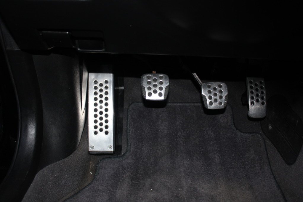
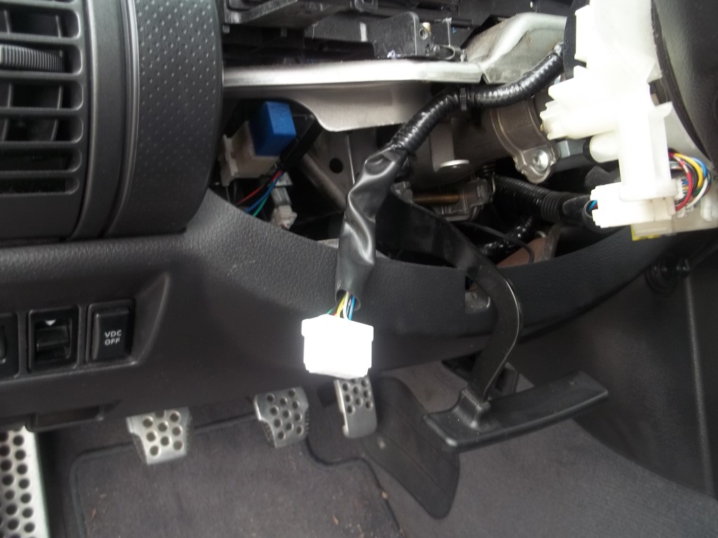
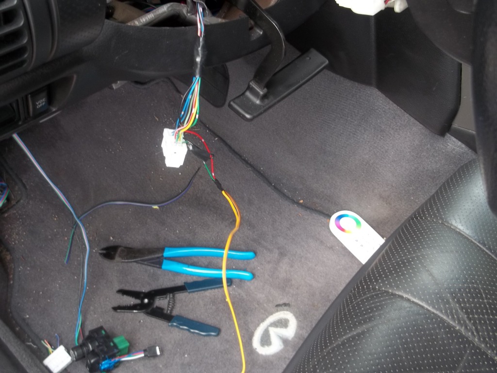
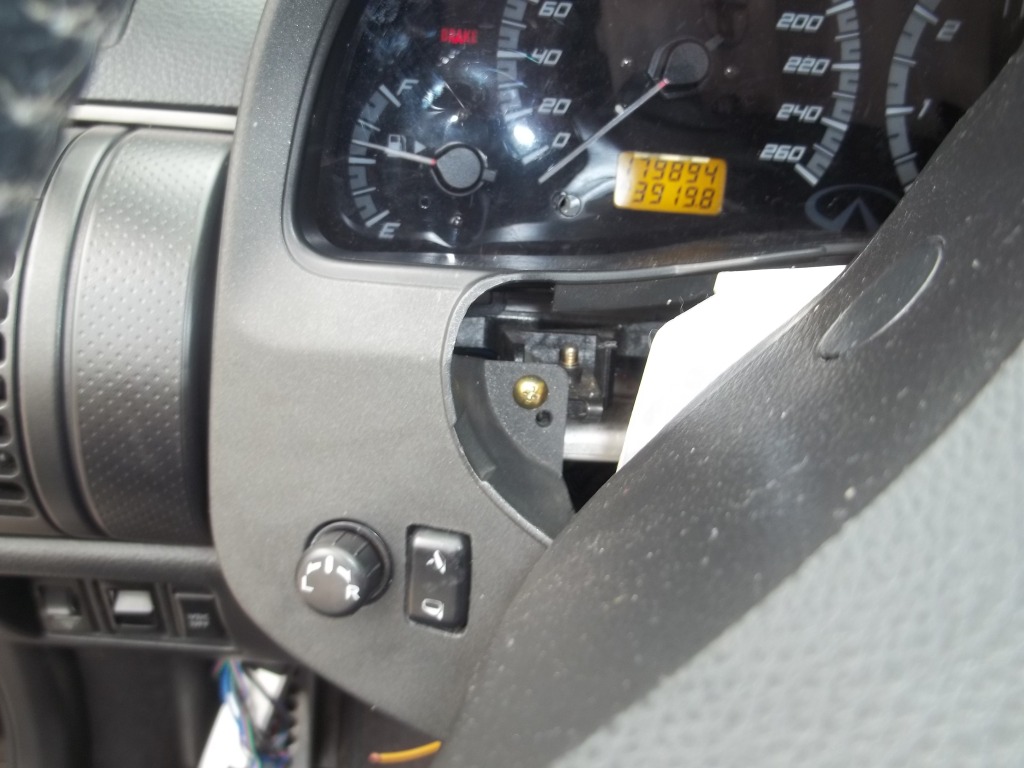
1. Remove the dead pedal and fuse panel piece by the driver Pedals. This is what you`ll have:

2. Loosten/remove the electrical tape/ties that hold the wiring tightly. This wiring goes to the fuse panel and your BCM (Body Control Module) and you`ll need better access to it
3. Disconnect the battery negative terminal
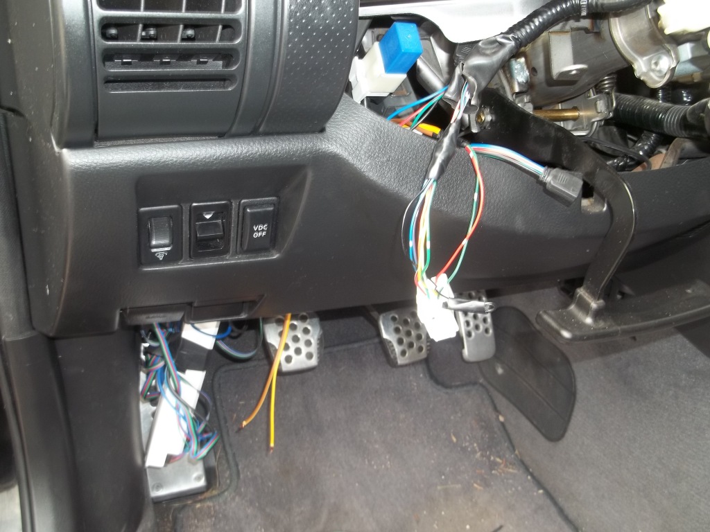
4. Locate the main power supply harness to the BCM. One wire is WHITE with a red tracer and the other is BLACK. They`re easy to find and closest to the firewall. Disconnect this harness for access:
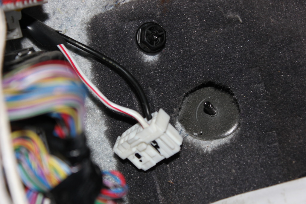
This is where I decided to get power from. If going this route, I highly advise you DO NOT run anything other than the mirrors off this wire. Ideally, you should run an independant wire from the battery, but that`s more work than is necessary for this.
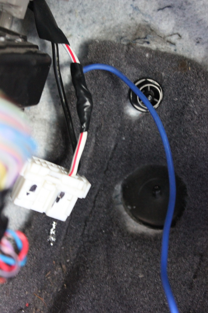
5. Splice the White with red trace wire and run a 12awg wire off it. This is your main Power supply to your new circuit. This wire is ALWAYS HOT even when the key is off, so be sure to take special care with this connection.
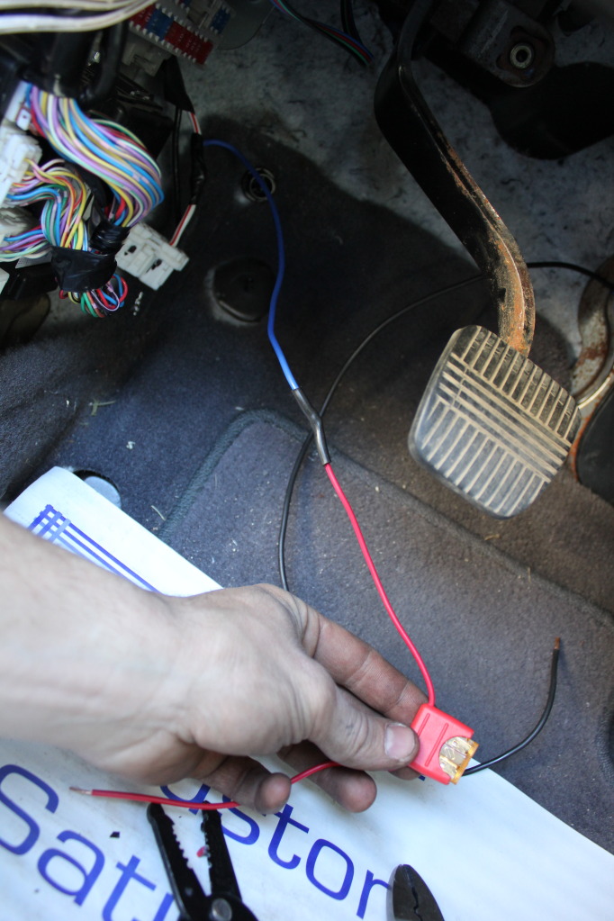
Also, fuse this wire IMMEDIATELY and as close to the connection as is reasonable. I for some reason added that blue extension of wire at first because I wasn't thinking. Just wire the fuse holder wire directly, as I did later (not shown)
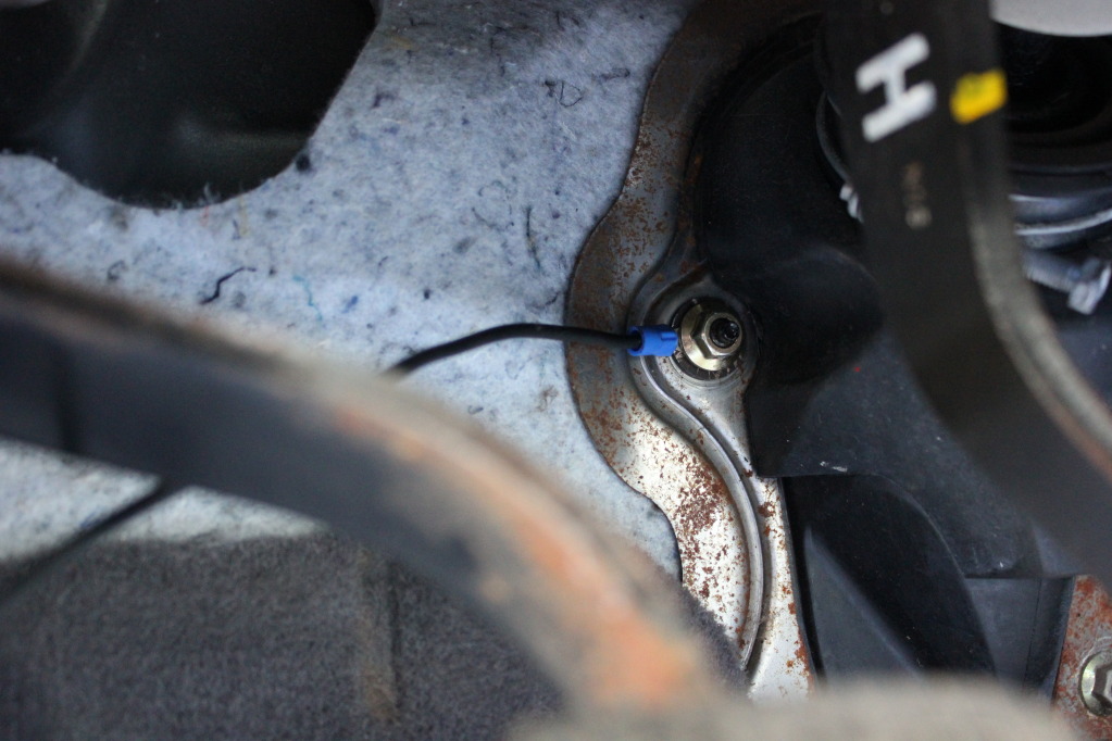
6. You`ve got power. Now get yourself a good ground for this circuit. Use 12awg and that Eyelette, I used the bracket where your steering column goes through the firewall. Just make sure it`s bare metal and grounds to chassis. This is your Main ground.
I've done a bunch of stuff to them. I'll get into that in the Main install DIY when it's ready.
I'm still in-process, but close enough to completion to put together and share this DIY.
First let me point out, I was determined to have an Automatic function for these mirrors. Very much so. It took a lot of time, research, drawing and testing to come up with a functional setup and the components to make it work.
The planning and research, and wiring mapping was a big undertaking, and frankly quite complicated, more than I expected. The good part of this story, is you don't have to do ANY of it. Just follow along
Second: This is NOT for installing your mirrors. This is NOT for wiring in the switch, or any of the disassembly/assembly that goes with that. I'll cover that later, if you have questions about that post in one of the many threads currently out on it that have discussed this stuff and I'll help you out:
https://g35driver.com/forums/g35-sed...r-goodies.html
https://g35driver.com/forums/g35-sed...-question.html
https://g35driver.com/forums/g35-sed...e-mirrors.html
Third: This thread is intended for those of you CAPABLE of doing wiring/crimping/soldering. You must understand at minimum the basics of such things to do this. If you need to know something you can't find through Google/Research, by all means ask, but simple stuff like "how to solder" or "how to run wiring", etc, is stuff I am assuming you already know if you're taking this on.
__________________________________________________ ____
Now, let's get down to it.
Supplies needed:
2x -- SPDT Relays. Like this http://www.ebay.com/itm/Lot5-Car-Tru...3e7e82&vxp=mtr
It might be easier for some if you get the ones with the harness already on there, Personally I prefer using spade terminals and crimping myself
1x -- 12awg x 5/16" Eyelette, crimp on style
12x -- 12awg med (regular) female spade terminals (if you didn't get pre-wired relays)
2x -- Fancy timer relays. This I hunted for, and still spent good money on the wrong stuff. Put your money up and buy the ones I'm linking you to, they're amazing, don't try to skimp here, it won't pay off, just buy two of these: http://www.smarthome.com/7279/Delay-...ELK-960/p.aspx
-12awg inline fuse holder
-5 amp fuse for holder
-Shrink tube/Electrical tape
-Solder (60/40 electrical solder)
-Soldering gun (25 Watt max)
-Small zip ties
2x -- 2-3 watt fast-switching diodes
-Side cutters, wire strippers, crimper tool, etc.
Wiring -- Preferably, you should have some 12awg and some 14-16awg for this project.
12awg is for the Main power/Ground wires and outputs to the motors.
14-16awg is for the trigger wires, and jumpers.
That should be about it but I'm probably missing something
-------------------------------------------------------
Where we're at:
1. You've already purchased all your components and have them ready to go, with your tools.
2. You've already installed your JDM mirrors, and run the folding motor wiring over to either the JDM switch, or to the BCM module/Fuse panel. This means you have 4 wires at this location that have now been, or are about to be, spliced into 2 wires
Now let's get to work:
1. Remove the dead pedal and fuse panel piece by the driver Pedals. This is what you`ll have:
2. Loosten/remove the electrical tape/ties that hold the wiring tightly. This wiring goes to the fuse panel and your BCM (Body Control Module) and you`ll need better access to it
3. Disconnect the battery negative terminal
4. Locate the main power supply harness to the BCM. One wire is WHITE with a red tracer and the other is BLACK. They`re easy to find and closest to the firewall. Disconnect this harness for access:
This is where I decided to get power from. If going this route, I highly advise you DO NOT run anything other than the mirrors off this wire. Ideally, you should run an independant wire from the battery, but that`s more work than is necessary for this.
5. Splice the White with red trace wire and run a 12awg wire off it. This is your main Power supply to your new circuit. This wire is ALWAYS HOT even when the key is off, so be sure to take special care with this connection.
Also, fuse this wire IMMEDIATELY and as close to the connection as is reasonable. I for some reason added that blue extension of wire at first because I wasn't thinking. Just wire the fuse holder wire directly, as I did later (not shown)
6. You`ve got power. Now get yourself a good ground for this circuit. Use 12awg and that Eyelette, I used the bracket where your steering column goes through the firewall. Just make sure it`s bare metal and grounds to chassis. This is your Main ground.
Last edited by TunerMax; 03-28-2013 at 11:42 AM.
#2
06-01-2012, 06:05 PM
Here's a good basic diagram of the SPDT relays you'll be using for this portion of the circuit:
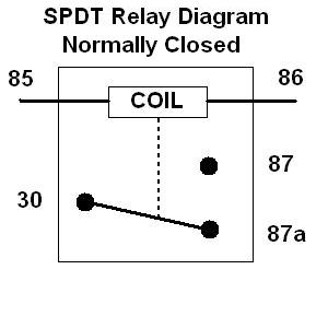
And here's the designations that you'll be connecting to:
RELAY #1 (FOLD OUT)
85 - Trigger from TIMER FOLD OUT relay [BCM Term 23 (Unlock)]
86 - Ground
30 - Out to Motor (Fold Out Wire)
87 - Positive power from BCM
87a - Ground
RELAY #2 (FOLD IN)
85 - Trigger from TIMER FOLD IN relay [BCM Term 30 (Lock)]
86 - Ground
30 - Out to Motor (Fold In Wire)
87 - Positive power from BCM
87a - Ground
It should be no surprise that this is going to get just a bit confusing once you start throwing wires together. So First things first, mark your SPDT relays. One will be marked FOLD IN and one FOLD OUT.
And if possible, use colour coded wires. You'll notice I used pretty much whatever I had, but I did make sure every different function got a different colour.
The following is common code but use what works for you:
Red - Positive
Black - Negative
Blue - Positive Trigger wire
Yellow - Positive Trigger wire
Doing this will only make everything a bunch easier. Do it for your sanity
I'll add pictures to this to help. Remember, your power feed will be split up to go to 4 relays. 2 SPDT shown above, then 2 of the Special timer relays.
Likewise, your ground will be split between 4 relays
I used a little junction block from the local surplus store to keep things tidy {pic to come}
{Running wires pictures and descriptions to come here}
Last edited by TunerMax; 03-28-2013 at 11:45 AM.
The following users liked this post:
G35Papa (06-03-2012)
#3
06-01-2012, 06:07 PM
TECHNICAL POST, FOR INFORMATION PURPOSES read at your own discretion:
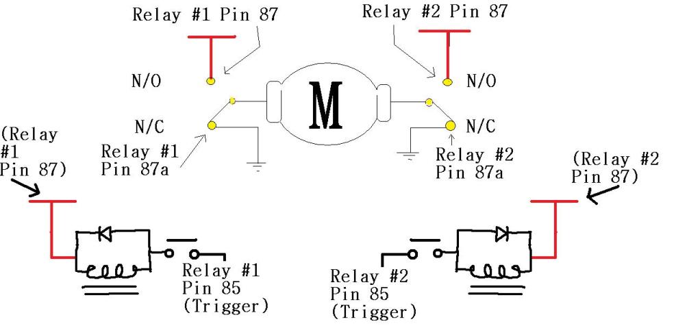
Here`s my artistic Wiring diagram, well, as much as is really needed. It might just confuse so disregard it if you`re bad with diagrams.
The main thing you need to know is just how to wire a normal Relay, so do some research on that and you`ll be fine. Heck you could probably just follow my pin designations without even knowing how to wire a relay if you really wanted to.
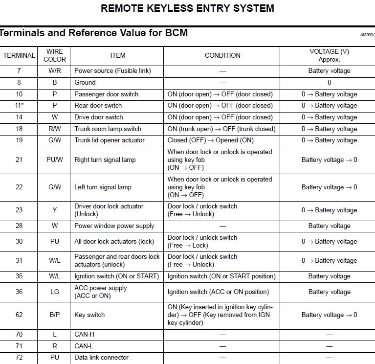
And here`s the BCM terminals you`ll want to use for your triggers to activate these relays.
Number 23 and Number 30 are the ones I chose. This causes the mirrors to function as follows:
LOCK button on Key fab or door: MIRRORS FOLD IN
UNLOCK button on Key fab or door: MIRRORS FOLD OUT
The Next part I want to explain, just so you understand what we're doing here.....you don't NEED to read this:
We're using the 2 SPDT Relays to keep things 'safe'. You can't just control the motor directly because it uses neutral wires. This is the same way your power windows work. Let's call the 2 wires going to the motor A and B.
When A is POSTITIVE, and B is negative, the motor Folds IN
When A is NEGATIVE, and B is POSITIVE, the motor Folds OUT.
All you're doing is reversing the polarities. But because these are NEUTRAL wires (the are used for both negative and positive), you can't just run your triggers right to them or you'll have a direct short.
So the relays make it work so that when sitting idle, both wires to the motor are grounded (NEGATIVE). When you activate one relay with the trigger, that wire becomes postive, now you have current flow through the motor.
If/When you trigger both relays at the same time, both wires become POSITIVE, and nothing happens, it's safe. (If you're confused, don't worry about it, I've figured this out and tested it, it will work. As long as you wire it properly everything is safe and functional)
We are using the Timer relays because you want the SPDT relays to work for about 10 seconds, or, however long it takes for the mirror to fold all the way out. Also, we are triggering this action with a "pulse" signal. That short instant when you press the Lock or Unlock button. We need it to create power for longer than that instant, so we are going to use these special relays to do it.
Here`s my artistic Wiring diagram, well, as much as is really needed. It might just confuse so disregard it if you`re bad with diagrams.
The main thing you need to know is just how to wire a normal Relay, so do some research on that and you`ll be fine. Heck you could probably just follow my pin designations without even knowing how to wire a relay if you really wanted to.
And here`s the BCM terminals you`ll want to use for your triggers to activate these relays.
Number 23 and Number 30 are the ones I chose. This causes the mirrors to function as follows:
LOCK button on Key fab or door: MIRRORS FOLD IN
UNLOCK button on Key fab or door: MIRRORS FOLD OUT
The Next part I want to explain, just so you understand what we're doing here.....you don't NEED to read this:
We're using the 2 SPDT Relays to keep things 'safe'. You can't just control the motor directly because it uses neutral wires. This is the same way your power windows work. Let's call the 2 wires going to the motor A and B.
When A is POSTITIVE, and B is negative, the motor Folds IN
When A is NEGATIVE, and B is POSITIVE, the motor Folds OUT.
All you're doing is reversing the polarities. But because these are NEUTRAL wires (the are used for both negative and positive), you can't just run your triggers right to them or you'll have a direct short.
So the relays make it work so that when sitting idle, both wires to the motor are grounded (NEGATIVE). When you activate one relay with the trigger, that wire becomes postive, now you have current flow through the motor.
If/When you trigger both relays at the same time, both wires become POSITIVE, and nothing happens, it's safe. (If you're confused, don't worry about it, I've figured this out and tested it, it will work. As long as you wire it properly everything is safe and functional)
We are using the Timer relays because you want the SPDT relays to work for about 10 seconds, or, however long it takes for the mirror to fold all the way out. Also, we are triggering this action with a "pulse" signal. That short instant when you press the Lock or Unlock button. We need it to create power for longer than that instant, so we are going to use these special relays to do it.
Last edited by TunerMax; 06-01-2012 at 09:27 PM.
The following users liked this post:
G35Papa (06-03-2012)
#4
06-01-2012, 06:08 PM
Finding your Trigger wires:
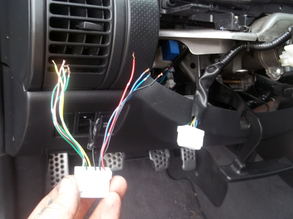
The harness you want is the second one up in this picture. It has already been removed from the BCM:
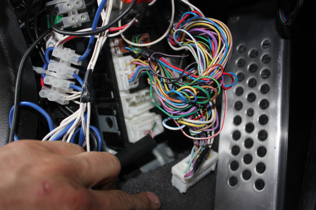
Here:
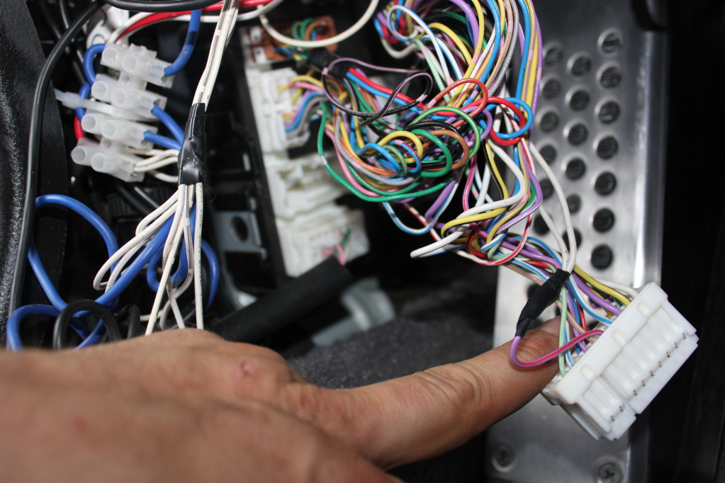
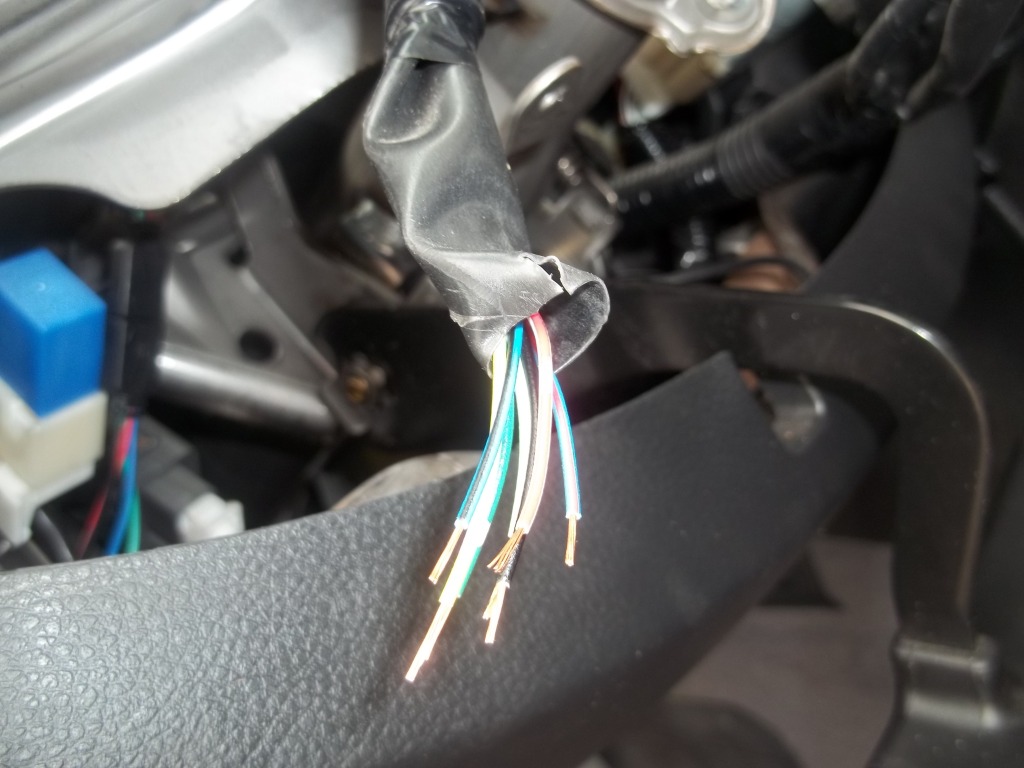
Ignore the wire with the Electrical tape on it in the picture below that's for my Puddle lights. Here's our 2 trigger wires. Don't depend on COLOUR code ok, it's probably different from the 03 to the 06. RELY ON THE TERMINAL LOCATION , that will be the same from 03-06. If in doubt count over from one side or the other according to my picture. Pink wire is the LOCK for your FOLD IN trigger, and the Yellow wire is the UNLOCK for your FOLD OUT trigger.
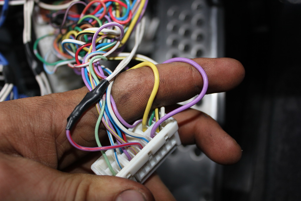
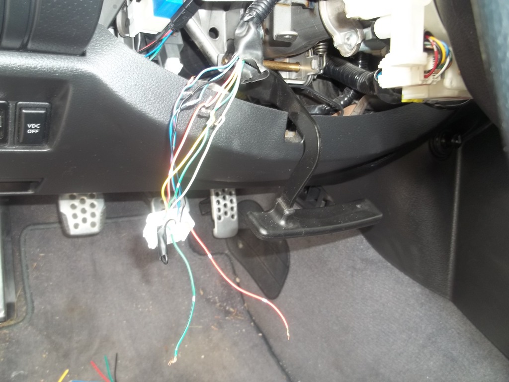
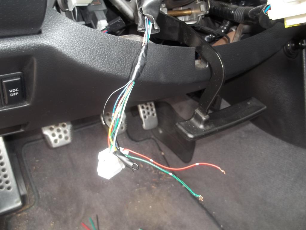
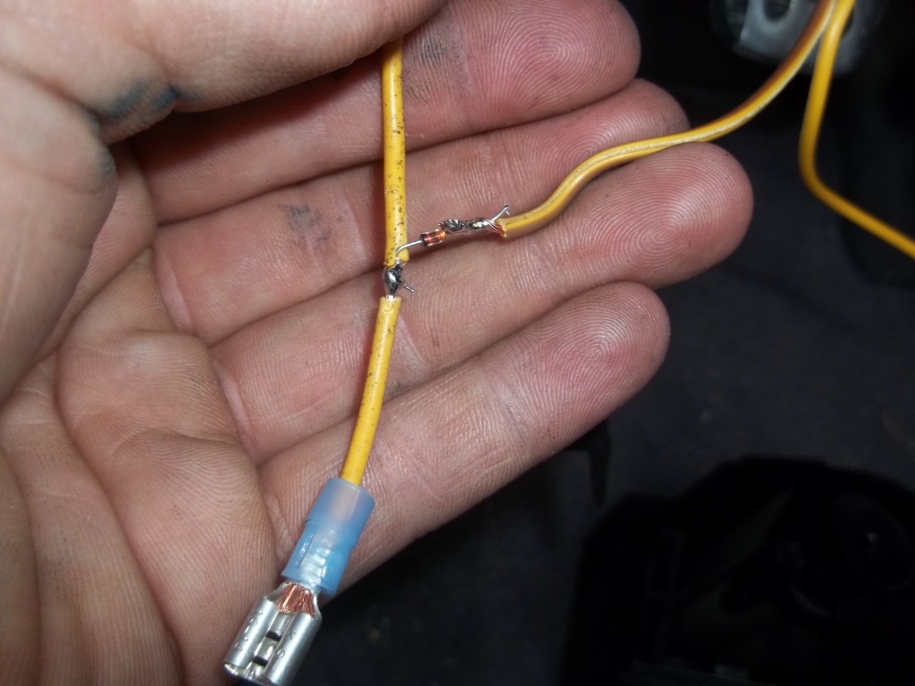
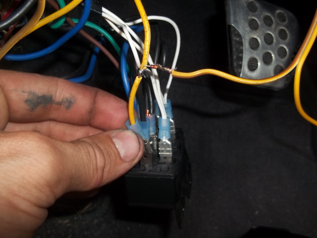
Splice these wires:
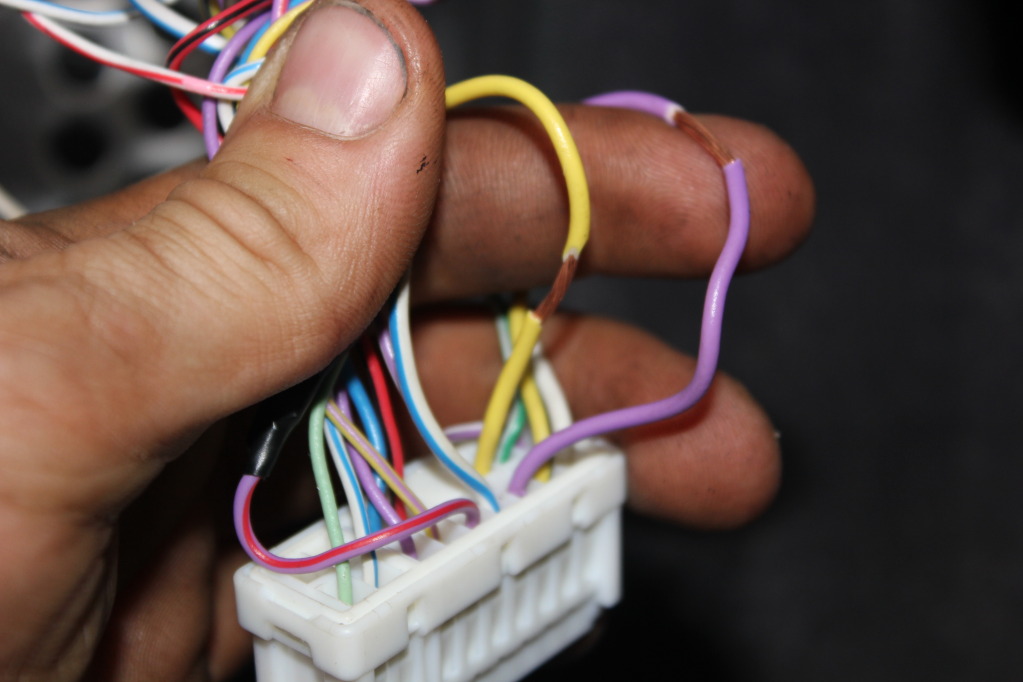
Solder a length of colour coded wire to each.
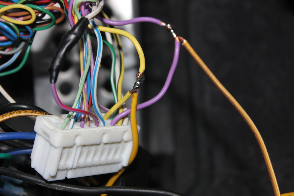
One will run to the Timer Relay #1 for FOLD OUT
One will run to the Timer Relay #2 for FOLD IN
The harness you want is the second one up in this picture. It has already been removed from the BCM:
Here:
Ignore the wire with the Electrical tape on it in the picture below that's for my Puddle lights. Here's our 2 trigger wires. Don't depend on COLOUR code ok, it's probably different from the 03 to the 06. RELY ON THE TERMINAL LOCATION , that will be the same from 03-06. If in doubt count over from one side or the other according to my picture. Pink wire is the LOCK for your FOLD IN trigger, and the Yellow wire is the UNLOCK for your FOLD OUT trigger.
Splice these wires:
Solder a length of colour coded wire to each.
One will run to the Timer Relay #1 for FOLD OUT
One will run to the Timer Relay #2 for FOLD IN
Last edited by TunerMax; 06-01-2012 at 09:39 PM.
The following users liked this post:
G35Papa (06-03-2012)
#5
06-01-2012, 06:09 PM
Special Timer Relays:
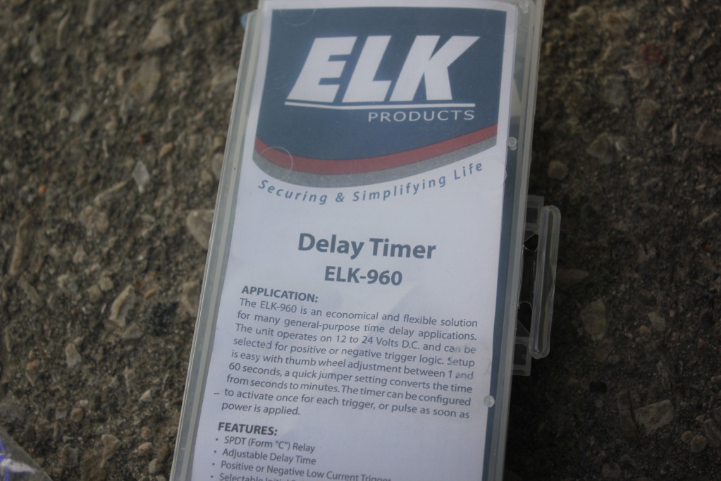
There's a Terminal block, and a bunch of settings for these. You can use these for a LOT of different stuff, read the instructions to get a quick idea of some of the adjsutments. The main ones you'll want:
Make sure the TRIGGER POLARITY is switched to POSTITIVE
{will fill in other settings soon with pics}
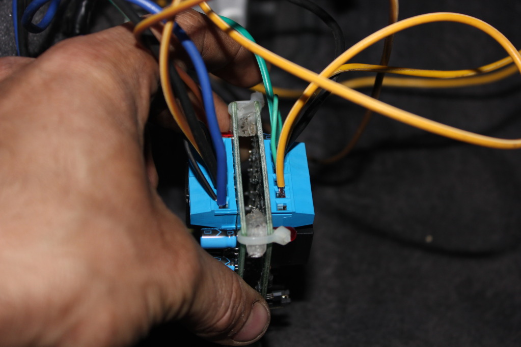
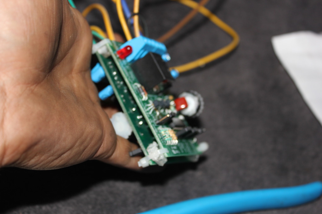
Have a look at the picture below, all your movable settings are set up properly in this picture, copy them:
You can see them here also:
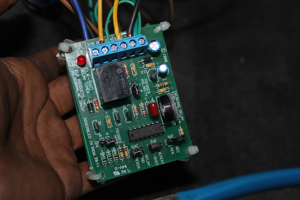
I'll get a better picture before any wires are hooked up, but for now:
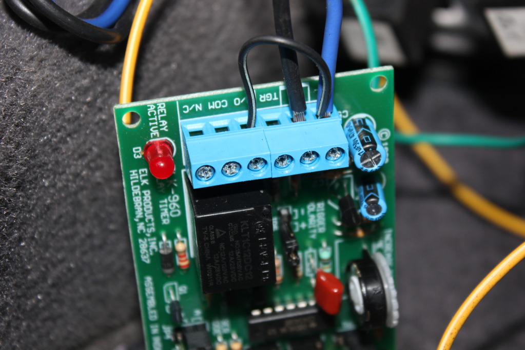
From Left to Right in the Above picture: Normally Closed;COM;Normally Open;Trigger;Negative;Positive
The Postive (Blue) comes from the fused power we tapped in earlier. You'll need to put a jumper from this over to the Normally Open terminal also.
The Negative comes from your main ground feed we got earlier.
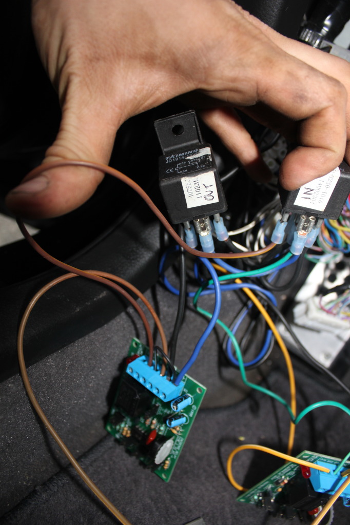
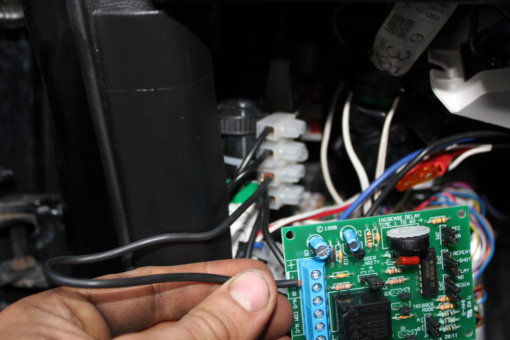
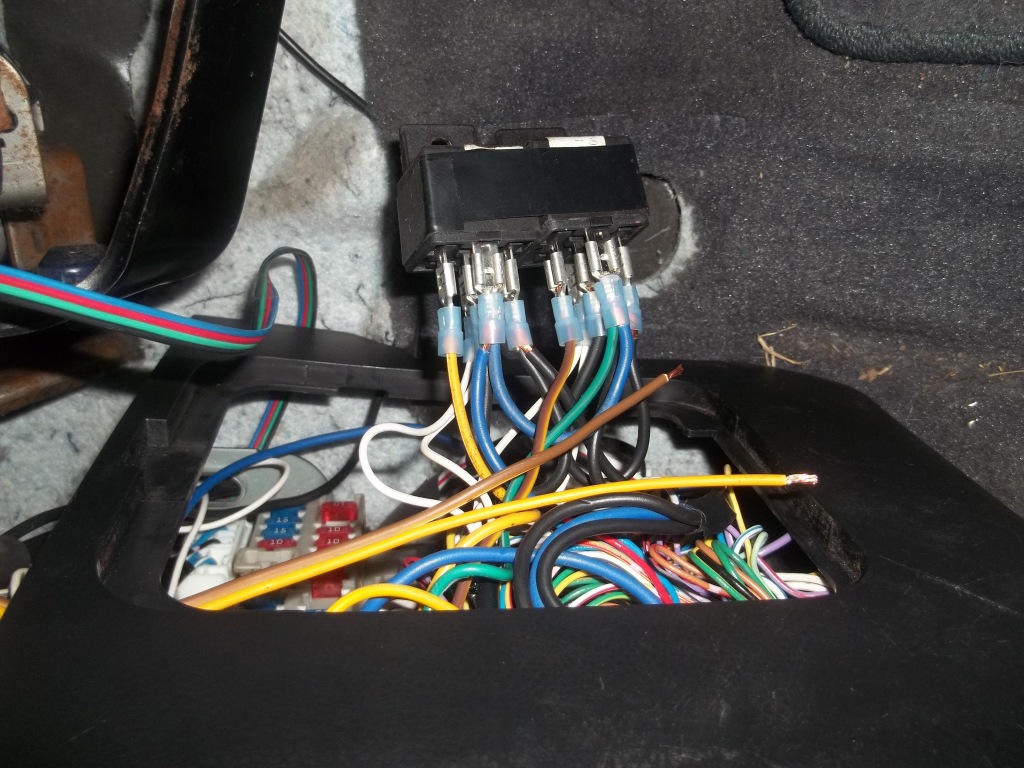
Here's a picture of me running the negative feed from my junction block I mentioned earlier:
This picture has a lot of wires, chill though, it's daunting but this is why we MARK and colour code everything
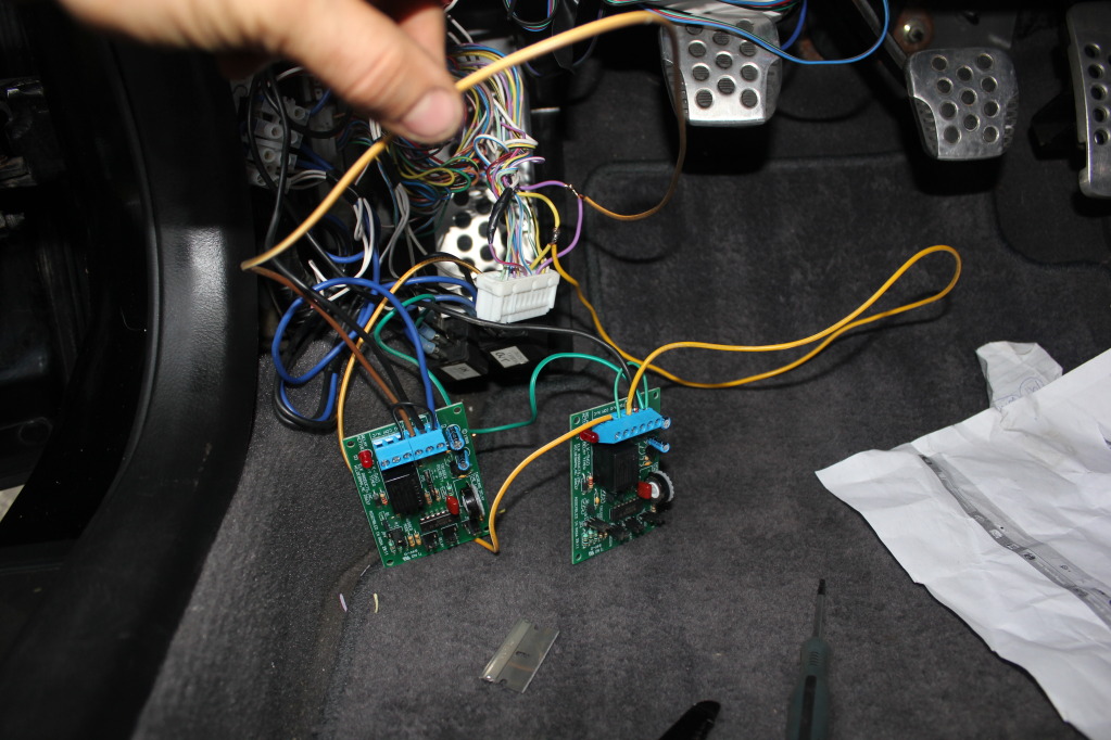
The Timer Relay on the RIGHT in this picture is for the UNLOCK (FOLD OUT)
The trigger wire I ran is YELLOW. You can run whatever colour you want.
The Timer Relay on the LEFT in this picture is for the LOCK (FOLD IN)
The trigger is the wire I'm holding, it's BROWN. You can run whatever colour you want.
----
Now, below is me running another brown wire to the FOLD IN SPDT relay we wired earlier. This is the OUTPUT from the Timer Relay. The Terminal on the Timer relay for this is the COM terminal.

Do the same thing from the FOLD OUT Timer relay to the FOLD OUT SPDT relay. These are the triggers that turn on the SPDT relays for the set time.
You'll need to hook the battery cable up to test now. Set the timer wheels to about 3 seconds longer than it actually takes to fold out the mirrors, and make sure to set them close to the same to one-another. The 3 second extra is for colder temps, where your mirrors will take longer to respond.
-------------------
Disconnect the battery again right after testing.
Now, mounting is up to you. For the time being I dremeled 4 holes in some plexiglass and cut them into small squares.
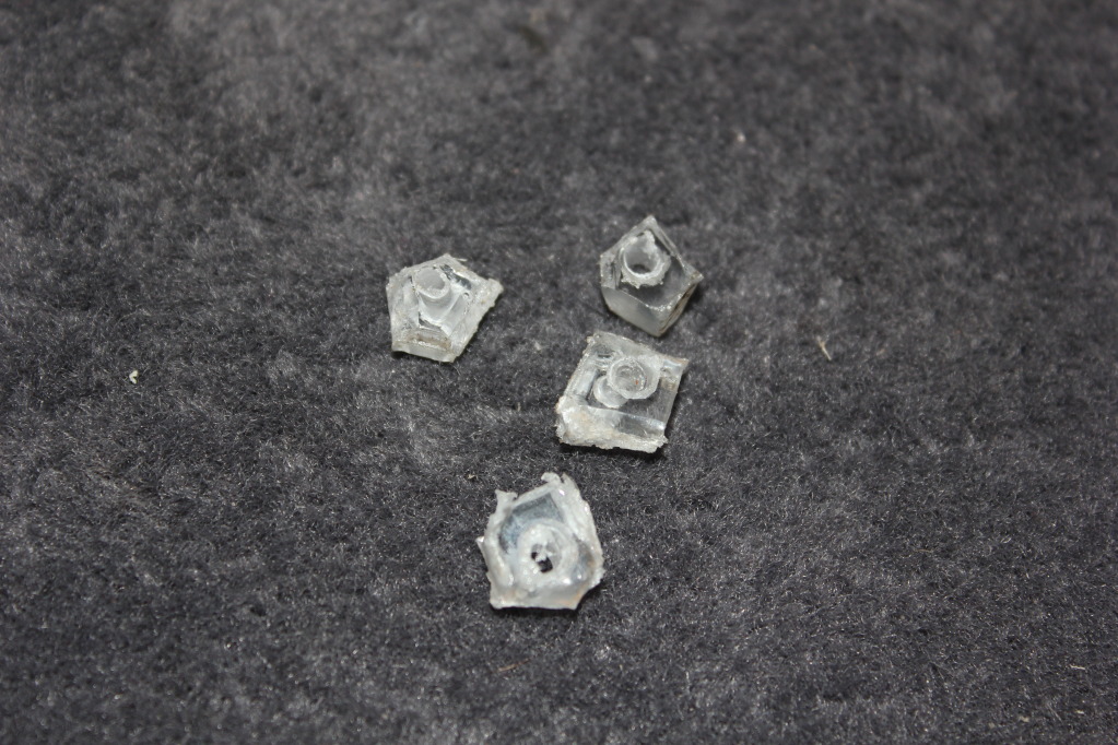
I placed these in between the Timer Relays so I could mount them together without any contacts touching. I wanted to save space. Be careful with this if you choose to do the same!!!
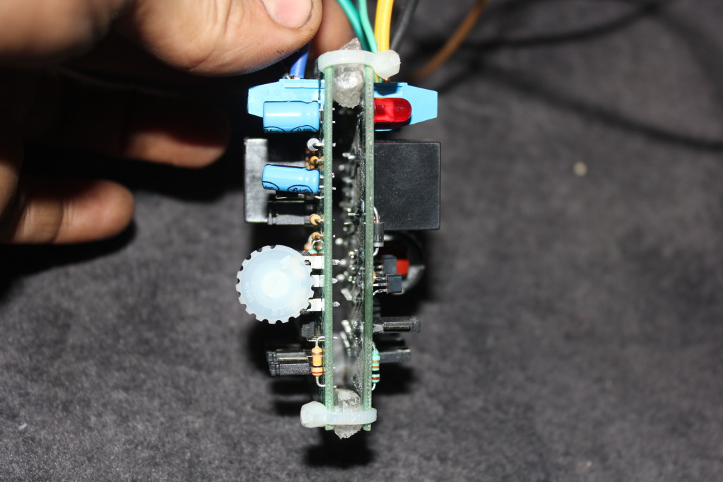
These are LIVE circuit boards as soon as you connect that battery. Make dammmmmed sure you protect them from touching any wires, steel, grounds, etc. You DO NOT want to risk frying your BCM. That 5 amp fuse is there, but it won't stop the triggers backfeeding through the BCM and frying it. TAKE YOUR TIME, make sure NOTHING is going to rub, tie everything up very nicely but not toooo tight, secure everything with screws or zip ties, just make sure it's done cleanly, and secure, and safe.
Then Re-assemble
There's a Terminal block, and a bunch of settings for these. You can use these for a LOT of different stuff, read the instructions to get a quick idea of some of the adjsutments. The main ones you'll want:
Make sure the TRIGGER POLARITY is switched to POSTITIVE
{will fill in other settings soon with pics}
Have a look at the picture below, all your movable settings are set up properly in this picture, copy them:
You can see them here also:
I'll get a better picture before any wires are hooked up, but for now:
From Left to Right in the Above picture: Normally Closed;COM;Normally Open;Trigger;Negative;Positive
The Postive (Blue) comes from the fused power we tapped in earlier. You'll need to put a jumper from this over to the Normally Open terminal also.
The Negative comes from your main ground feed we got earlier.
Here's a picture of me running the negative feed from my junction block I mentioned earlier:
This picture has a lot of wires, chill though, it's daunting but this is why we MARK and colour code everything
The Timer Relay on the RIGHT in this picture is for the UNLOCK (FOLD OUT)
The trigger wire I ran is YELLOW. You can run whatever colour you want.
The Timer Relay on the LEFT in this picture is for the LOCK (FOLD IN)
The trigger is the wire I'm holding, it's BROWN. You can run whatever colour you want.
----
Now, below is me running another brown wire to the FOLD IN SPDT relay we wired earlier. This is the OUTPUT from the Timer Relay. The Terminal on the Timer relay for this is the COM terminal.
Do the same thing from the FOLD OUT Timer relay to the FOLD OUT SPDT relay. These are the triggers that turn on the SPDT relays for the set time.
You'll need to hook the battery cable up to test now. Set the timer wheels to about 3 seconds longer than it actually takes to fold out the mirrors, and make sure to set them close to the same to one-another. The 3 second extra is for colder temps, where your mirrors will take longer to respond.
-------------------
Disconnect the battery again right after testing.
Now, mounting is up to you. For the time being I dremeled 4 holes in some plexiglass and cut them into small squares.
I placed these in between the Timer Relays so I could mount them together without any contacts touching. I wanted to save space. Be careful with this if you choose to do the same!!!
These are LIVE circuit boards as soon as you connect that battery. Make dammmmmed sure you protect them from touching any wires, steel, grounds, etc. You DO NOT want to risk frying your BCM. That 5 amp fuse is there, but it won't stop the triggers backfeeding through the BCM and frying it. TAKE YOUR TIME, make sure NOTHING is going to rub, tie everything up very nicely but not toooo tight, secure everything with screws or zip ties, just make sure it's done cleanly, and secure, and safe.
Then Re-assemble
Last edited by TunerMax; 06-01-2012 at 10:13 PM.
The following users liked this post:
G35Papa (06-03-2012)
#6
06-01-2012, 06:11 PM
NOW>>>>>>>>>>I'm repeating this from the OP for the time being:
There's a little complication. Your JDM toggle switch. If you want to use it (probably, right?), you'll need to tap the output of the JDM toggle switch into this Circuit.
This will be done with DIODES to prevent reverse current flow. I haven't installed this yet, so I'm leaving this open for now until I can verify my wiring plan and take pictures of the process. If you guys need any more specifics from what I've already posted please inform so that I can take pics when I take it apart to integrate the toggle switch.
EDIT: SWITCH DONE, Instructions below:
Apologies in advance for crappy pics, I didn't have my good camera on me. Something is better than nothing though, right?
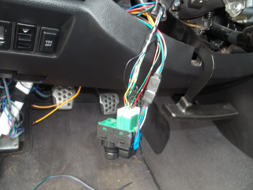
Remove your center console trim, unplug the USDM switch:
Here's your JDM switch harness:
Cut off the old USDM switch harness, strip wires:
Match up the colours. Note the the small tracer colours. Terminal designation is different on the JDM switch but the colours should be the same:
^ You can butt-connect, solder, whatever you prefer for joining/splicing wires. Personally I soldered my wires for longevity. Shrink tube is always preferred but I ran out of it so i just electrical taped it really well
The 2 wires that aren't connected are the outputs to the FOLD IN/FOLD OUT relays.
Hook up a length of wire to each so that you can wire them down to your Relays
Run wires
Below you'll note extra wire harness, disregard it, that's for my RGB lighting. Also I taped off my Illumination wire on the JDM harness (black wire). If you want to use this for your Switch light just hook the ground up to any illumination ground in the car. The Dimmer switch is closeby.
Hooking up the switch
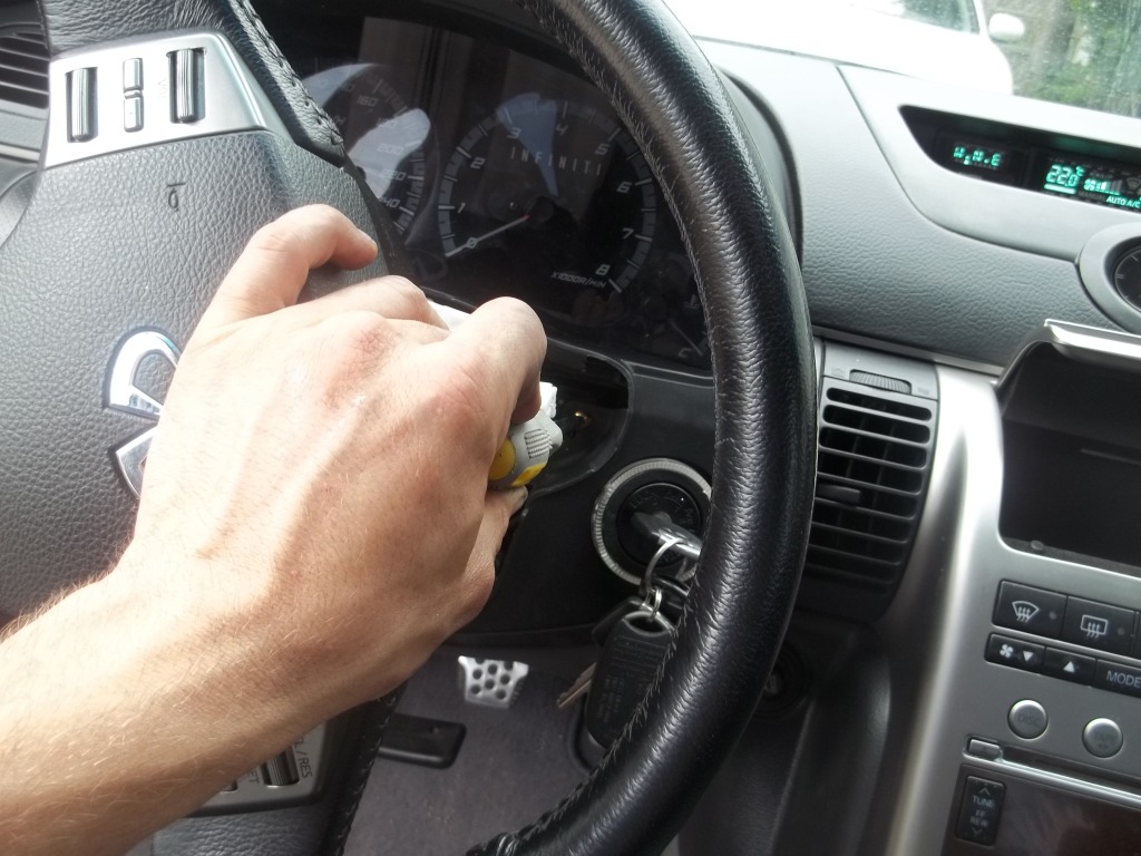
Tip: turn the steering wheel to access the bolts for the console trim:
Now, run those 2 wires down to your fold in/fold out relays:
You'll need to test this.
Turn the key to the "ON" position to power the JDM switch unit.
Touch and hold one of the wires from the JDM switch up to your FOLD IN relay trigger (TERMINAL 86)
Press the JDM switch toggle to the FOLD IN position. Note function. If nothing happens, repeat this step with the OTHER wire from the JDM switch unit.
Now that you've identified the proper Wire for FOLD IN, hook it up with your diode:
The marked (black) line on the Diode goes toward the load. In this case, the RELAY SIDE. This allows power to flow from the JDM switch trigger wire into the relay but not the other way.
Re-test, if it works, you've hooked the diode up correctly. Now repeat this procedure with the other JDM switch trigger wire, and hook it up to the FOLD OUT relay terminal #86.
Obviously wrap/shrink tube this connection as well and tie everything up all neat and tidy
Now you're good to go!
You will be able to control your folding mirrors via. remote, lock/unlock button, or manually with the JDM switch toggle.
Enjoy
And the puddle lights are custom, they don't come with the JDM mirrors.
I'll be uploading pics and fixing this DIY up until it's whole and complete over the next few days. I ran out of time today, apologies!
There's a little complication. Your JDM toggle switch. If you want to use it (probably, right?), you'll need to tap the output of the JDM toggle switch into this Circuit.
This will be done with DIODES to prevent reverse current flow. I haven't installed this yet, so I'm leaving this open for now until I can verify my wiring plan and take pictures of the process. If you guys need any more specifics from what I've already posted please inform so that I can take pics when I take it apart to integrate the toggle switch.
EDIT: SWITCH DONE, Instructions below:
Apologies in advance for crappy pics, I didn't have my good camera on me. Something is better than nothing though, right?
Remove your center console trim, unplug the USDM switch:
Here's your JDM switch harness:
Cut off the old USDM switch harness, strip wires:
Match up the colours. Note the the small tracer colours. Terminal designation is different on the JDM switch but the colours should be the same:
^ You can butt-connect, solder, whatever you prefer for joining/splicing wires. Personally I soldered my wires for longevity. Shrink tube is always preferred but I ran out of it so i just electrical taped it really well
The 2 wires that aren't connected are the outputs to the FOLD IN/FOLD OUT relays.
Hook up a length of wire to each so that you can wire them down to your Relays
Run wires
Below you'll note extra wire harness, disregard it, that's for my RGB lighting. Also I taped off my Illumination wire on the JDM harness (black wire). If you want to use this for your Switch light just hook the ground up to any illumination ground in the car. The Dimmer switch is closeby.
Hooking up the switch
Tip: turn the steering wheel to access the bolts for the console trim:
Now, run those 2 wires down to your fold in/fold out relays:
You'll need to test this.
Turn the key to the "ON" position to power the JDM switch unit.
Touch and hold one of the wires from the JDM switch up to your FOLD IN relay trigger (TERMINAL 86)
Press the JDM switch toggle to the FOLD IN position. Note function. If nothing happens, repeat this step with the OTHER wire from the JDM switch unit.
Now that you've identified the proper Wire for FOLD IN, hook it up with your diode:
The marked (black) line on the Diode goes toward the load. In this case, the RELAY SIDE. This allows power to flow from the JDM switch trigger wire into the relay but not the other way.
Re-test, if it works, you've hooked the diode up correctly. Now repeat this procedure with the other JDM switch trigger wire, and hook it up to the FOLD OUT relay terminal #86.
Obviously wrap/shrink tube this connection as well and tie everything up all neat and tidy
Now you're good to go!
You will be able to control your folding mirrors via. remote, lock/unlock button, or manually with the JDM switch toggle.
Enjoy
And the puddle lights are custom, they don't come with the JDM mirrors.
I'll be uploading pics and fixing this DIY up until it's whole and complete over the next few days. I ran out of time today, apologies!
Last edited by TunerMax; 06-25-2012 at 08:42 AM.
The following 3 users liked this post by TunerMax:


#10
06-01-2012, 10:19 PM
LOL thought I kind of rounded that up in the long-winded OP
Also, it can be noted, this Wiring diagram will work for ANY Folding mirror as long as the mirror has an INTERNAL limit swich. Cefiro ones do, and the G ones do, I'd assume most/all others are the same but don't know for sure.
Only difference in the Circuit would be where you get power/triggers from. Principle is the same. This message is for all those dudes hunting online for a way to do this!!!! Cause I was one of them for months, and I found NOTHING....... Not one thread or person that had done this.
The wiring was complex to figure out, and I'm sure that's why.
[COLOR="darkorange"]
Third: This thread is intended for those of you CAPABLE of doing wiring/crimping/soldering. You must understand at minimum the basics of such things to do this. If you need to know something you can't find through Google/Research, by all means ask, but simple stuff like "how to solder" or "how to run wiring", etc, is stuff I am assuming you already know if you're taking this on.
Third: This thread is intended for those of you CAPABLE of doing wiring/crimping/soldering. You must understand at minimum the basics of such things to do this. If you need to know something you can't find through Google/Research, by all means ask, but simple stuff like "how to solder" or "how to run wiring", etc, is stuff I am assuming you already know if you're taking this on.
Also, it can be noted, this Wiring diagram will work for ANY Folding mirror as long as the mirror has an INTERNAL limit swich. Cefiro ones do, and the G ones do, I'd assume most/all others are the same but don't know for sure.
Only difference in the Circuit would be where you get power/triggers from. Principle is the same. This message is for all those dudes hunting online for a way to do this!!!! Cause I was one of them for months, and I found NOTHING....... Not one thread or person that had done this.
The wiring was complex to figure out, and I'm sure that's why.

#12
06-02-2012, 10:17 AM
It's the subtle features of a car that often make it the most desirable, despite what we like to tell ourselves.
Its those little things that make the day to day back and forth to work better. Stuff Like auto-dimming mirrors, memory seats, power seats, etc.
At least, that's my weak attempt to justify doing this. In truth, it's bling factor mainly.
However it is nice if you park on the street or in tight quarters. But that's pretty much where the functionality of it ends. The rest is for looks and 'cool' factor.
Was it worth it to me to undergo this huge wiring fiasco? Yes. So I fully think it's MORE than worth it to someone who already has these mirrors to be able to simply follow the DIY, not have to think toooo much, and get the same feature.
I've only had this for a day and it's already turning heads when I park and lock the car in public.
#13
06-02-2012, 03:00 PM

Registered User
