
Daytime Running Light aka DRL Set Up (US Models)


Thread Starter
|
Registered User
Joined: Apr 2008
Posts: 72
Likes: 1
From: East Amherst, NY
Daytime Running Lights aka DRL Set Up (US Models)
Thanks to Kevin at KP Technologies for his support. I'd highly recommend his products and his technical knowledge of Nismo electronics. Always check out http://www.kptechnologies.com/before you try to get too "tricky" on your own. Besides the many modules they produce, KP carries quality relays and other required parts.
This is the general set up for using a weather proof Bosch-style relay to emulate the DRL configuration used by Canadian G35s - DRLs - as most are aware - are required in Canada by law. This set up will also help Canadian buyers of US Infiniti products that need the DRL conversion done (and probably safer than having Crappy Tire try to install a DRL module). For US drivers - it also provides an add'l insurance discount in most US States for having permanent DRLs.
The following was done on my 2008 G35xS (sedan). The goal was to put the fogs in use as DRLs - yet retain all the normal headlight/fog light switch functions.
This conversion was done with a Bosch-style 5 pin weatherproof relay (weatherproof as it will be protected but still sitting underneath the IPDM in the engine compartment). KP Technologies supplied the 30A weatherproof relay with the 5 wire harness included. There are specifics that require a shop manual for the G (at least if you want it to be an hour or less of a job), but the general relay connections are:
Pin 30 (Common) � Output to both fog light wires (must cut wire). Terminate output end to fogs. Connect end from IPDM harness to relay.
Pin 87A (NC) � Fused ignition power (MAKE SURE this is a switched source not directly connected to the IPDM - the PWM relay nearby is a good choice and described below)
Pin 87 (NO) � Output from IPDM to fog lights (there are two fog outputs - Left & Right - see below for the specific wire colors)
Pin 85 (Coil +) � Parking light (+) wire or headlight (low/high). Important as this is what ultimately retains the original headlight/fog light switch functions.
Pin 86 (Coil -) - Ground (to the NEG (-) terminal on battery is usually convenient and easy to secure)
It's a good idea to install an inline fuse (15A) for the wire to Pin 87A and use Solder Seal weather proof connections (or similar) for all splices.
All switch functions will operate normally. When the headlights are on - via AUTO or turned on manually, the DRL FOGS drop out via the relay and the FOG LIGHT ON/OFF switch will work as normal.
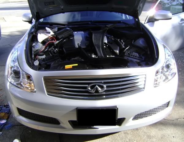
See pics for a view of how it looks (I'll repost some pics with "less glare" later - it's just so sunny all the time here in Western NY!)
LIGHT SWITCH IN OFF or AUTO POSITION (DAYTIME) - DRLs ON WHEN CAR IS RUNNING

LIGHT SWITCH IN ON POSITION or AUTO (IF DARK) - DRLs OFF WHEN CAR IS RUNNING and HEADLIGHTS/PARKING LIGHTS ON

LIGHT SWITCH IN ON POSITION or AUTO (IF DARK) AND FOG SWITCH ON - DRLs OFF (FOG SWITCH CONTROLS FOGS ON/OFF STATUS)

Did a quick tear down for pics. NOTE: Not sure the harness wire colors will always be the same, so I'd reference the pin numbers on the relay more so than the colors of the harness I used - these represent the harness I bought from from Kevin at KPT and colors may vary harness to harness.

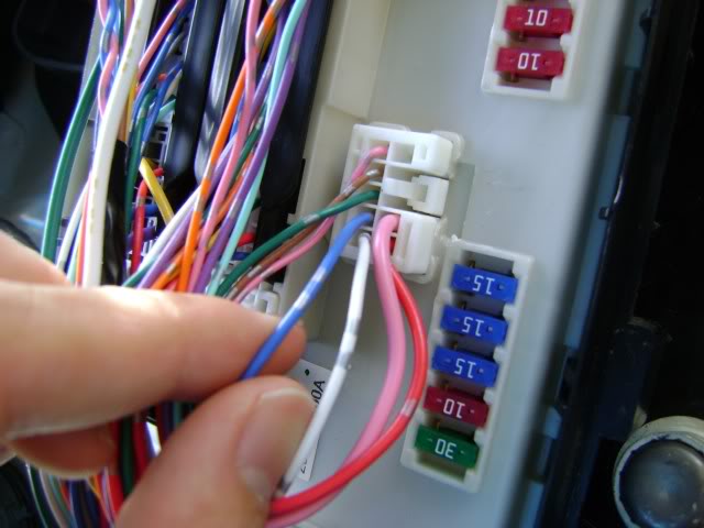
After you open the cover on the IPDM, locate the small harness with the fog light wires. Cut and terminate the medium blue w/silver wire (RED CIRCLE) and cut white w/silver and connect to pin 87 (green on my harness) and GREEN CIRCLE in pic.
Connect the red w/silver wire from harness to pin 85 (white on my harness) YELLOW CIRCLE in pic.
Pin 86 is connected to the negative terminal on the battery (blue wire on my harness).
Pin 30 is for the fog light wires going to the bulbs - med blue w/ silver and white w/silver (black on my harness)
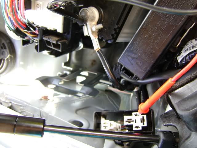
Pin 87A is for the SWITCHED power connection - I used the PWM relay located on the side of the engine compartment. See the YELLOW lined box in the pic below. (red wire on my harness)

This box was tough to get open but the location is good for a proximity to all the other connections - AND it is not powered off the IPDM which is very important. The RED oval in the pic shows the power wire with a fuse holder (15A) that we installed. This wire goes to pin 86.
We used Solder Seal connectors for a good splice and to gain weather proofing. NOTE: I'm in Western NY and snow & road salt are a way of life, so a good seal is key. Other than a little digging, it is a pretty easy job. Let me know if questions.
This is the general set up for using a weather proof Bosch-style relay to emulate the DRL configuration used by Canadian G35s - DRLs - as most are aware - are required in Canada by law. This set up will also help Canadian buyers of US Infiniti products that need the DRL conversion done (and probably safer than having Crappy Tire try to install a DRL module). For US drivers - it also provides an add'l insurance discount in most US States for having permanent DRLs.
The following was done on my 2008 G35xS (sedan). The goal was to put the fogs in use as DRLs - yet retain all the normal headlight/fog light switch functions.
This conversion was done with a Bosch-style 5 pin weatherproof relay (weatherproof as it will be protected but still sitting underneath the IPDM in the engine compartment). KP Technologies supplied the 30A weatherproof relay with the 5 wire harness included. There are specifics that require a shop manual for the G (at least if you want it to be an hour or less of a job), but the general relay connections are:
Pin 30 (Common) � Output to both fog light wires (must cut wire). Terminate output end to fogs. Connect end from IPDM harness to relay.
Pin 87A (NC) � Fused ignition power (MAKE SURE this is a switched source not directly connected to the IPDM - the PWM relay nearby is a good choice and described below)
Pin 87 (NO) � Output from IPDM to fog lights (there are two fog outputs - Left & Right - see below for the specific wire colors)
Pin 85 (Coil +) � Parking light (+) wire or headlight (low/high). Important as this is what ultimately retains the original headlight/fog light switch functions.
Pin 86 (Coil -) - Ground (to the NEG (-) terminal on battery is usually convenient and easy to secure)
It's a good idea to install an inline fuse (15A) for the wire to Pin 87A and use Solder Seal weather proof connections (or similar) for all splices.
All switch functions will operate normally. When the headlights are on - via AUTO or turned on manually, the DRL FOGS drop out via the relay and the FOG LIGHT ON/OFF switch will work as normal.
See pics for a view of how it looks (I'll repost some pics with "less glare" later - it's just so sunny all the time here in Western NY!)
LIGHT SWITCH IN OFF or AUTO POSITION (DAYTIME) - DRLs ON WHEN CAR IS RUNNING
LIGHT SWITCH IN ON POSITION or AUTO (IF DARK) - DRLs OFF WHEN CAR IS RUNNING and HEADLIGHTS/PARKING LIGHTS ON
LIGHT SWITCH IN ON POSITION or AUTO (IF DARK) AND FOG SWITCH ON - DRLs OFF (FOG SWITCH CONTROLS FOGS ON/OFF STATUS)
Did a quick tear down for pics. NOTE: Not sure the harness wire colors will always be the same, so I'd reference the pin numbers on the relay more so than the colors of the harness I used - these represent the harness I bought from from Kevin at KPT and colors may vary harness to harness.
After you open the cover on the IPDM, locate the small harness with the fog light wires. Cut and terminate the medium blue w/silver wire (RED CIRCLE) and cut white w/silver and connect to pin 87 (green on my harness) and GREEN CIRCLE in pic.
Connect the red w/silver wire from harness to pin 85 (white on my harness) YELLOW CIRCLE in pic.
Pin 86 is connected to the negative terminal on the battery (blue wire on my harness).
Pin 30 is for the fog light wires going to the bulbs - med blue w/ silver and white w/silver (black on my harness)
Pin 87A is for the SWITCHED power connection - I used the PWM relay located on the side of the engine compartment. See the YELLOW lined box in the pic below. (red wire on my harness)
This box was tough to get open but the location is good for a proximity to all the other connections - AND it is not powered off the IPDM which is very important. The RED oval in the pic shows the power wire with a fuse holder (15A) that we installed. This wire goes to pin 86.
We used Solder Seal connectors for a good splice and to gain weather proofing. NOTE: I'm in Western NY and snow & road salt are a way of life, so a good seal is key. Other than a little digging, it is a pretty easy job. Let me know if questions.
Last edited by klossfam; Oct 2, 2008 at 05:27 PM. Reason: Pin Detail Correction

Thread Starter
|
Registered User
Joined: Apr 2008
Posts: 72
Likes: 1
From: East Amherst, NY
Additional DRL Info for Relay Install
Per my DRL instructions above, please be aware it applies to 2007+ Gs only as there were some changes to the electrical routing etc on the Gen II Gs. Also, the service manual was close but not exact. In addition, weather proofing splices is a good idea, even if everything is semi-protected under the battery cover. I would have a trusted auto electrician help you if you aren't a doing this day to day. I worked with an independent small foreign chain that has a great reputation. Most should charge an hour to an hour and a half of labor (plus you can get a receipt that has "DRL relay installed" or similar to give to your insurance agent if you are in the States). As long as you ID the right wires first, it is just one or two cuts, a little wire routing and bundling for a clean job and you are good to go.


Registered User
Joined: May 2007
Posts: 143
Likes: 0
From: Mississippi
Ive been waiting for this for a long time. Thanks for the info
Can you please list which relay switch we need for this from KP Tech?
Also, are there instructions that come with the relay switch?
Thanks
Can you please list which relay switch we need for this from KP Tech?
Also, are there instructions that come with the relay switch?
Thanks
Trending Topics

Thread Starter
|
Registered User
Joined: Apr 2008
Posts: 72
Likes: 1
From: East Amherst, NY
KPT sells the relays for multiple purposes as well as selling their own kits...No instructions as this is info that Kevin at KPT really did as a very nice favor to myself and the G35Driver community. It would be good to buy the relays from KPT since he has been so helpful...The link to the relay and harness is:
http://www.kptechnologies.com/ Go to PRODUCTS, then RELAYS/RELAY PACKS, then choose RELAYS - the 30A Waterproof is the one ($6.99)...
http://www.kptechnologies.com/ Go to PRODUCTS, then RELAYS/RELAY PACKS, then choose RELAYS - the 30A Waterproof is the one ($6.99)...
The only thing "special" about our relay is the fact it is weatherproof and can be mounted under the hood. Most standard automotive relays are not designed to be mounted under the hood.
Any 30A or bigger weather proof relay should work the same!
Any 30A or bigger weather proof relay should work the same!
Just performed the wiring today on my 08, with all the great information from klossfam/Jeff. Definitely a great mod, and pretty easy overall; I found it really fun to perform, and as a novice to this modification arena, I'd definitely recommend this to any do it yourselfer.
It took me longer than expected because 1) my soldering iron was really rusted and it took me forever to get solder to melt properly -- speaking of which, thank goodness for Clear Bra as a big glob fell right on the fender, but luckily dried and slipped right off; and 2) the PWM relay box for the switched power is pretty tricky to gain access and solder onto with its placement in tight quarters. Overall, it took me about 4 hours, but that included a half-hour interlude to run down to the local electronics store for that inline 15A fuse.
I took some snaps just to supplement klossfam's pictures above and will be glad to share them in a few days.
I feel safer already driving around with these DRLs
Just to supplement klossfam's already great work:
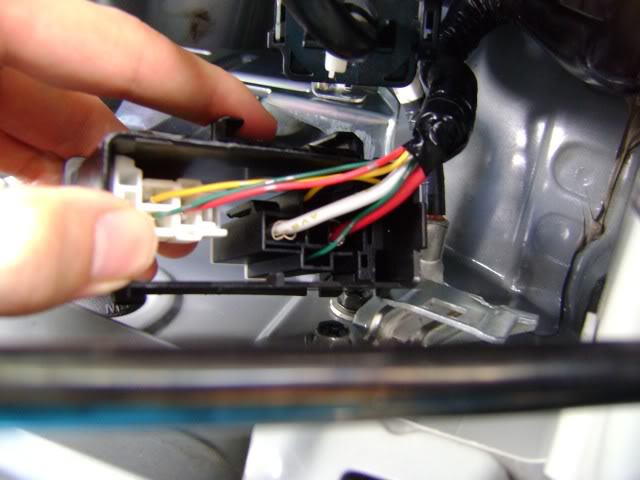
The 86-88 pins on the IPDM up close:
Determining which terminal to use for the switched power in the PWM relay
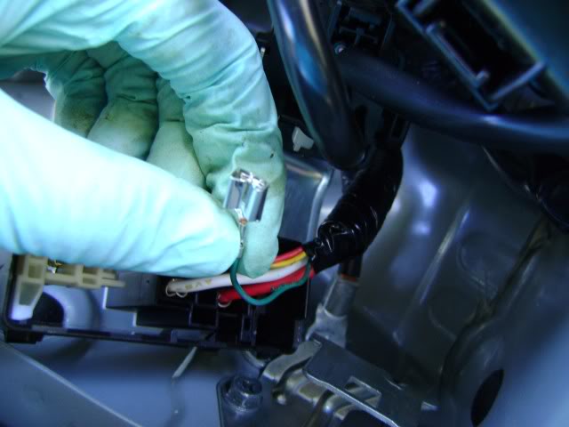
From the underside of the relay, the green one is the one we want:
Getting ready to solder onto the green:
The IPDM all done, just getting ready to tape/wrap things up:

Lights off:

Lights on:
The 86-88 pins on the IPDM up close:
Determining which terminal to use for the switched power in the PWM relay
From the underside of the relay, the green one is the one we want:
Getting ready to solder onto the green:
The IPDM all done, just getting ready to tape/wrap things up:
Lights off:
Lights on:
Thread Starter
|
Registered User
Joined: Apr 2008
Posts: 72
Likes: 1
From: East Amherst, NY
Great Job prech! You probably had the same thought I did after the job was done: Why doesn't Infiniti just use one design for US/Canada - like Toyota, Audi et al - and just put DRLs on all their cars! You probably saw the DTRL fuse in the IPDM...they leave the fuse in to taunt people like us who like to do minor mods...My previous car (2006 Audi A4) even had a master DRL switch and my wife's 08 Highlander Limited has DRLs off/DRLs on with Auto Headlights/etc...On a humorous side note, we are seeing if we can switch OFF the DRLs on my son's 06 V-Dub Rabbit and activate the city lights/parking lights to be the DRLs (using the VAG-Com cable and software)...

