

Zeitronix Zt-2 Install Plus Utec EMS


Zeitronix Zt-2 Install DIY with Pics
wanted to do a DIY guide as i have found nothing for the Zt-2 Zeitronic and G35/350Z
Here are pdf instructions for Zt-2
http://www.zeitronix.com/installatio...structions.pdf
ECU pinout
http://www.innovatemotorsports.com/r...5_G35_350z.php
and
http://www.cj-motorsports.com/03pinout.htm
Huge thanks to Marc from www.zeitronix.com for all his help !
Zeitronix are fantastic when it comes to support, if you buy a zeitronix then you will always have someone there to help you! I can’t believe the speed at which they reply, im very impressed

Other Notes I have read
Newest instructions do not require 8 - Brown to be grounded.
- Pre 2010 models will use this if they have another sensor they want grounded but it wont show up on the LCD
- Post 2010 models can use this wire to display info from additions sensors on the LCD
One brown wire is for Zt-2 MAP ground (11) second one (8) for standalone EMS with differential wideband input
User1 (Zt2-pin 12) blue wire is for any 0-5 volt type sensor reading like boost. knock etc.
Only wires you 100% you need to connect for just the Zt-2 to run are
1. Red (12V)
3. Green (tach/rpm)
7. Black (Ground)
10. Gray (tps)
If you have a Zeitronix MAP Boost sensor then you need to connect 4, 6 and 11
Here are pdf instructions for Zt-2
http://www.zeitronix.com/installatio...structions.pdf
ECU pinout
http://www.innovatemotorsports.com/r...5_G35_350z.php
and
http://www.cj-motorsports.com/03pinout.htm
Huge thanks to Marc from www.zeitronix.com for all his help !
Zeitronix are fantastic when it comes to support, if you buy a zeitronix then you will always have someone there to help you! I can’t believe the speed at which they reply, im very impressed
Other Notes I have read
Newest instructions do not require 8 - Brown to be grounded.
- Pre 2010 models will use this if they have another sensor they want grounded but it wont show up on the LCD
- Post 2010 models can use this wire to display info from additions sensors on the LCD
One brown wire is for Zt-2 MAP ground (11) second one (8) for standalone EMS with differential wideband input
User1 (Zt2-pin 12) blue wire is for any 0-5 volt type sensor reading like boost. knock etc.
Only wires you 100% you need to connect for just the Zt-2 to run are
1. Red (12V)
3. Green (tach/rpm)
7. Black (Ground)
10. Gray (tps)
If you have a Zeitronix MAP Boost sensor then you need to connect 4, 6 and 11
Last edited by R6n350GT; May 15, 2011 at 06:38 AM.
Installation:
Step 1: Wind windows down, take off positive battery terminal
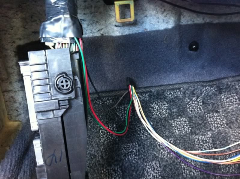
Step 2: Remove ECU, there is a little tab you push and then the handle pulls down and the ECU just comes off.
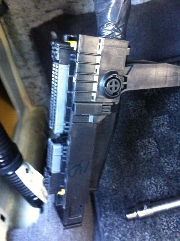
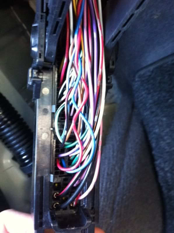
Step 3: Remove the inner black cover and also the tape that hold the sleeve on the wires. Then roll the sleeve up to expose the wires.
Step 4: Wire 1 � Red : Switched positive connected to ECU pink pin #119 or 120
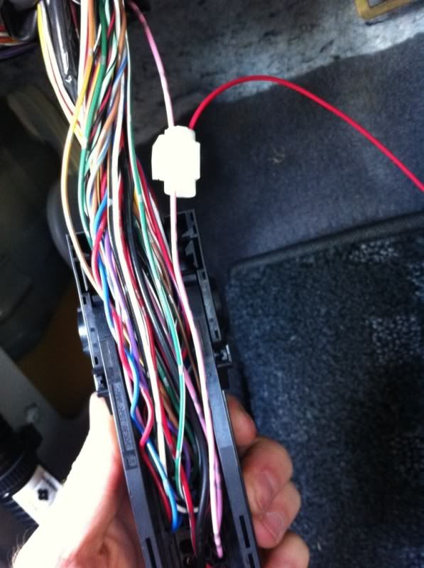
Step 5: Wire 3 � Green : RPM connected to ECU yellow/red pin #62
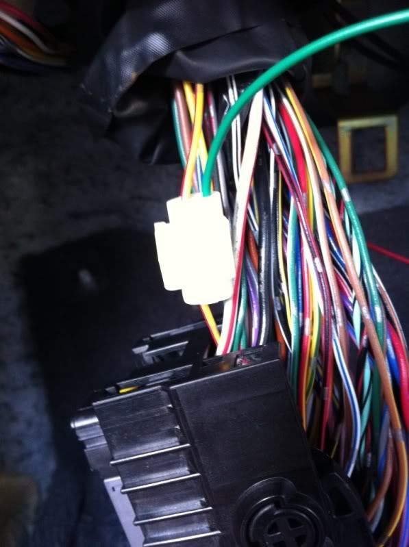
Step 6: Wire 7 � Black: Ground connected to ECU thick black pin #1, #115 or #116

Step 7: Wire 10 � Grey: TPS connected to ECU green (US), white (JDM) pin #50

Step 8: Tape the wires back up, pull sleeve down and then tape the sleeve
Step 9: Push ECU back into place, push the leaver back up.
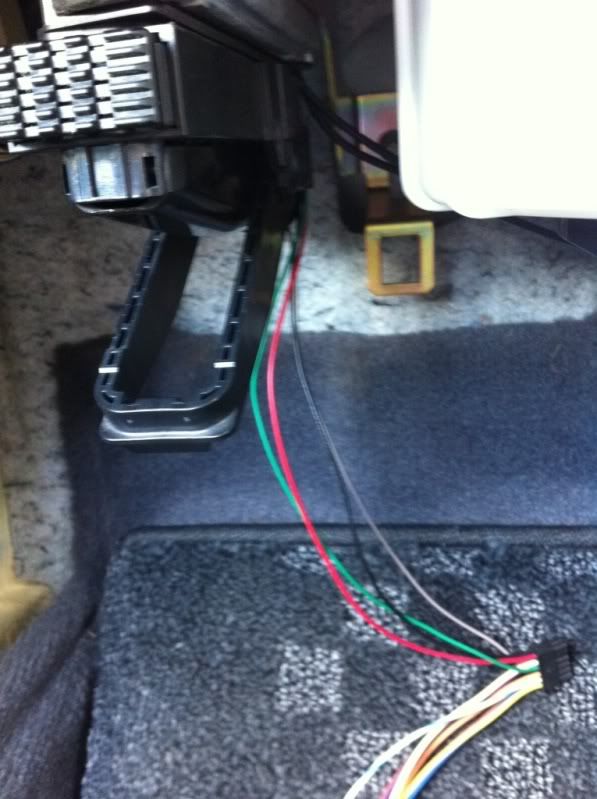
Step 10: Mounting the Zt-2. I used 3M dual lock Velcro, just a bit up at the back so when I wedge the zt-2 in between the cabin filter and ECU it will hold. Connect all your wires. The dual adapter goes into DATA, then the cable that runs to the LCD plugs into it, and then another cable runs from the dual adapter to the serial to USB adapter for the laptop. I keep the serial to usb adapter in the upper glove box as I have no DVD player

Installing LCD
Step 1: Take out the BOSE stereo
Drill a hold either on the left or right, in the higher corner of the upper cubby.
It is actually easier to drill from the outside.

Step 2: Use 3M Dual lock volctro to mount the bracket. I used a heavy duty door hinge, I picked one that would not open and close easy, the more fused the better.


Step 3: Run the LCD wire through the hole and then cable tie it along outside of the glove box to the Zt-2 box
Open:
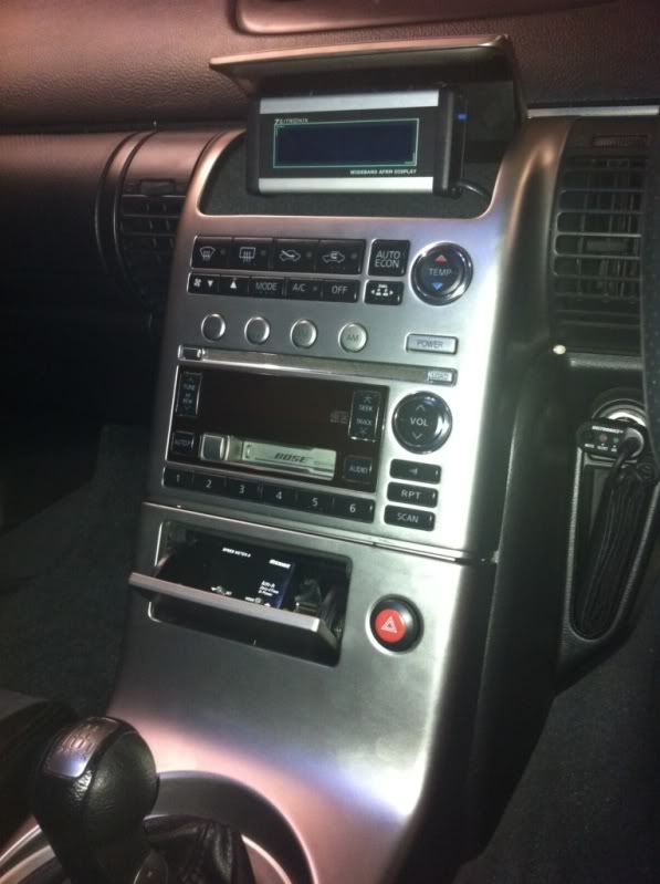
Half close (closes all the way for complete stock look!)

All turned on !

Zeitronix Software:
If you have the Belkin serial to USB adapter and have trouble with windows 7 and drivers then here is the solution!
http://www.clearchain.com/blog/posts...bit-mac-osx-10

Your Done!
I have not covered the EGT probe or the O2 probe as I have not got the turbo installed so no point.
I will update when I get the HKS 3037 ST kit installed
Step 1: Wind windows down, take off positive battery terminal
Step 2: Remove ECU, there is a little tab you push and then the handle pulls down and the ECU just comes off.
Step 3: Remove the inner black cover and also the tape that hold the sleeve on the wires. Then roll the sleeve up to expose the wires.
Step 4: Wire 1 � Red : Switched positive connected to ECU pink pin #119 or 120
Step 5: Wire 3 � Green : RPM connected to ECU yellow/red pin #62
Step 6: Wire 7 � Black: Ground connected to ECU thick black pin #1, #115 or #116
Step 7: Wire 10 � Grey: TPS connected to ECU green (US), white (JDM) pin #50
Step 8: Tape the wires back up, pull sleeve down and then tape the sleeve
Step 9: Push ECU back into place, push the leaver back up.
Step 10: Mounting the Zt-2. I used 3M dual lock Velcro, just a bit up at the back so when I wedge the zt-2 in between the cabin filter and ECU it will hold. Connect all your wires. The dual adapter goes into DATA, then the cable that runs to the LCD plugs into it, and then another cable runs from the dual adapter to the serial to USB adapter for the laptop. I keep the serial to usb adapter in the upper glove box as I have no DVD player
Installing LCD
Step 1: Take out the BOSE stereo
Drill a hold either on the left or right, in the higher corner of the upper cubby.
It is actually easier to drill from the outside.
Step 2: Use 3M Dual lock volctro to mount the bracket. I used a heavy duty door hinge, I picked one that would not open and close easy, the more fused the better.
Step 3: Run the LCD wire through the hole and then cable tie it along outside of the glove box to the Zt-2 box
Open:
Half close (closes all the way for complete stock look!)
All turned on !
Zeitronix Software:
If you have the Belkin serial to USB adapter and have trouble with windows 7 and drivers then here is the solution!
http://www.clearchain.com/blog/posts...bit-mac-osx-10
Your Done!
I have not covered the EGT probe or the O2 probe as I have not got the turbo installed so no point.
I will update when I get the HKS 3037 ST kit installed
Last edited by R6n350GT; May 15, 2011 at 07:00 AM.

Thread
Thread Starter
Forum
Replies
Last Post