
Works Bell Paddle Shifters! (56k Go Away!)


Joined: May 2003
Posts: 1,820
Likes: 3
From: Warshington
Works Bell Paddle Shifters! (56k Go Away!)
So I was one of the lucky 3 that got one of the WB Paddle Shifter kits from ASpec down in SoCal. First all the "thanks." Logan at ASpec was AWESOME. He was pleasant to speak on the phone, which is seems to be pretty uncommon with sales/service positions these days. After purchasing late Friday, he had it out the door to me with a tracking number on Monday, and it was delivered on Thursday, installed that night. And boy, what fun they are.
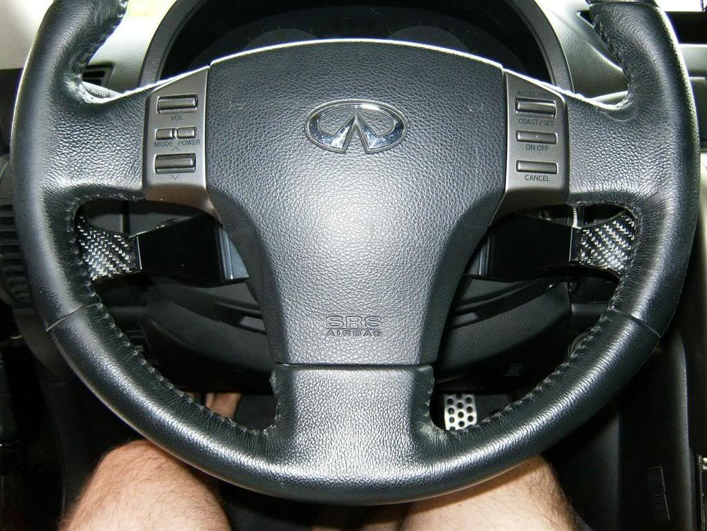
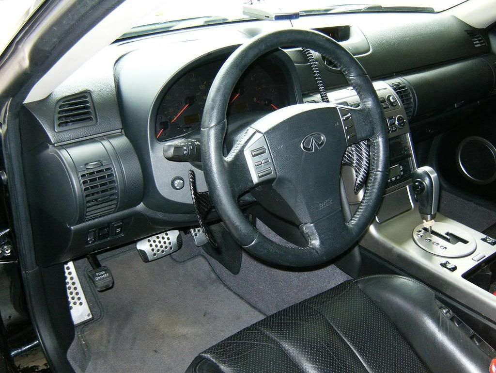
 I was worried that they'd be too low for a 9-3 grip on the steering wheel, but they line up nicely with my pinky/ring fingers and don't feel intrusive.

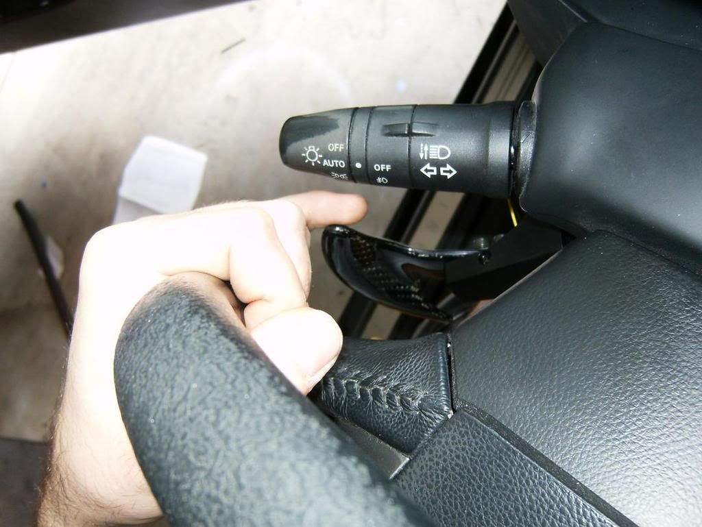
The pull is very minimal, and the shifts are indeed as fast as using the shifter ****. (I'll try and mess with videos later.) Even with mild turning, I found it's easy to access the paddles. You can adjust them to be much higher, but they will interfere with the turn stalk and wiper stalk (if turning left, or with the wipers on max). Also, if you really demand higher/closer paddles, it would be fairly easy to machine your own brackets with the switch housings further forward and higher up. Personally, I thought I was going to mess with making my own CF paddles, but I'm in no rush for now.
The box came wrapped nicely, with each individual part/assembly in its out sealed wrapping.
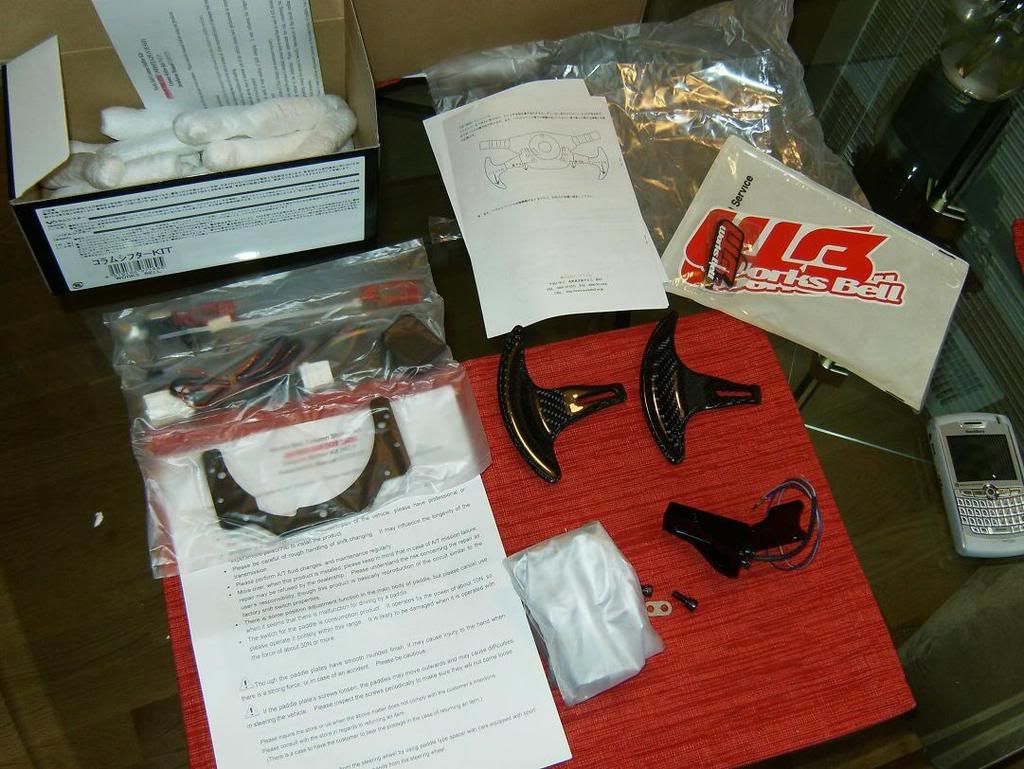
They even threw in a key chain with the stickers.

The guys at ASpec translated the instructions from Japanese and included the directions with their own install pictures (from a G35) for my G35.
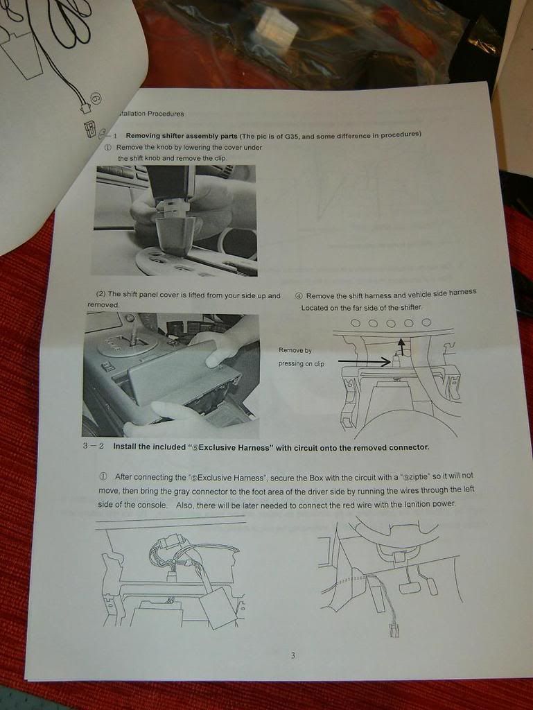
The one item that made the install take 2 minutes longer (yes, 2 minutes ) was the translated instructions were in black and white, and theres one point where you have to pin up a connector (really easy) and it made figuring out which wires go where more difficult. However, given that the Japanese instructions were also included and had colored steps, I simply referred to that diagram, and voila, good to go!
Now, onto the parts:
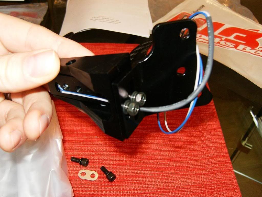
The switch housings and brackets are made out of black metal and have adjustments for raising and lowering, as well as twisting.
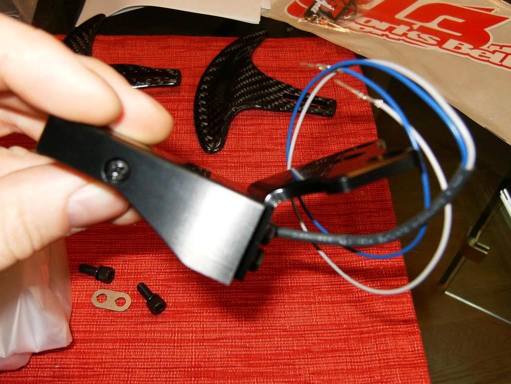
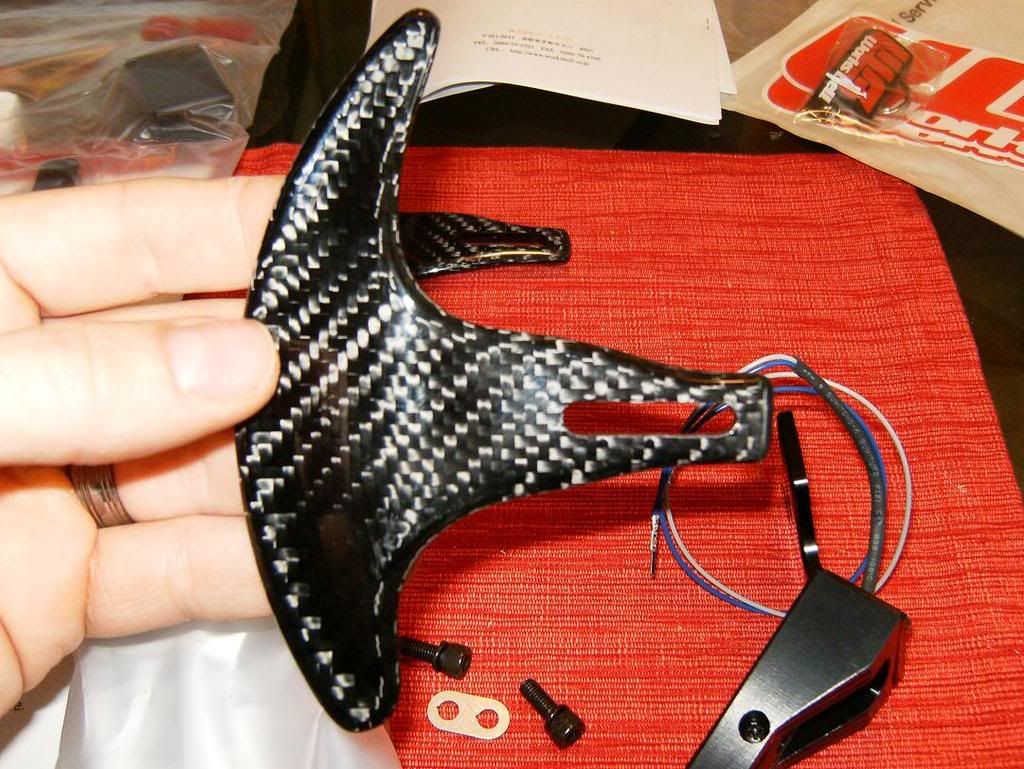
The paddles themselves have a glassy feel to them, but are CF.
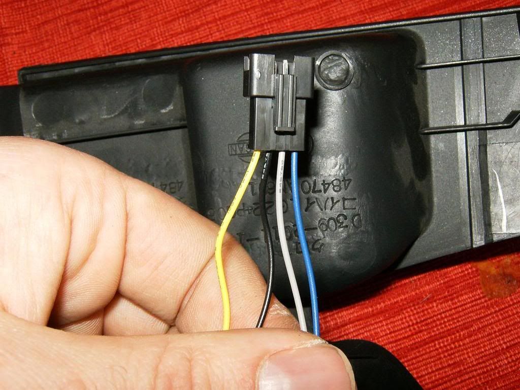
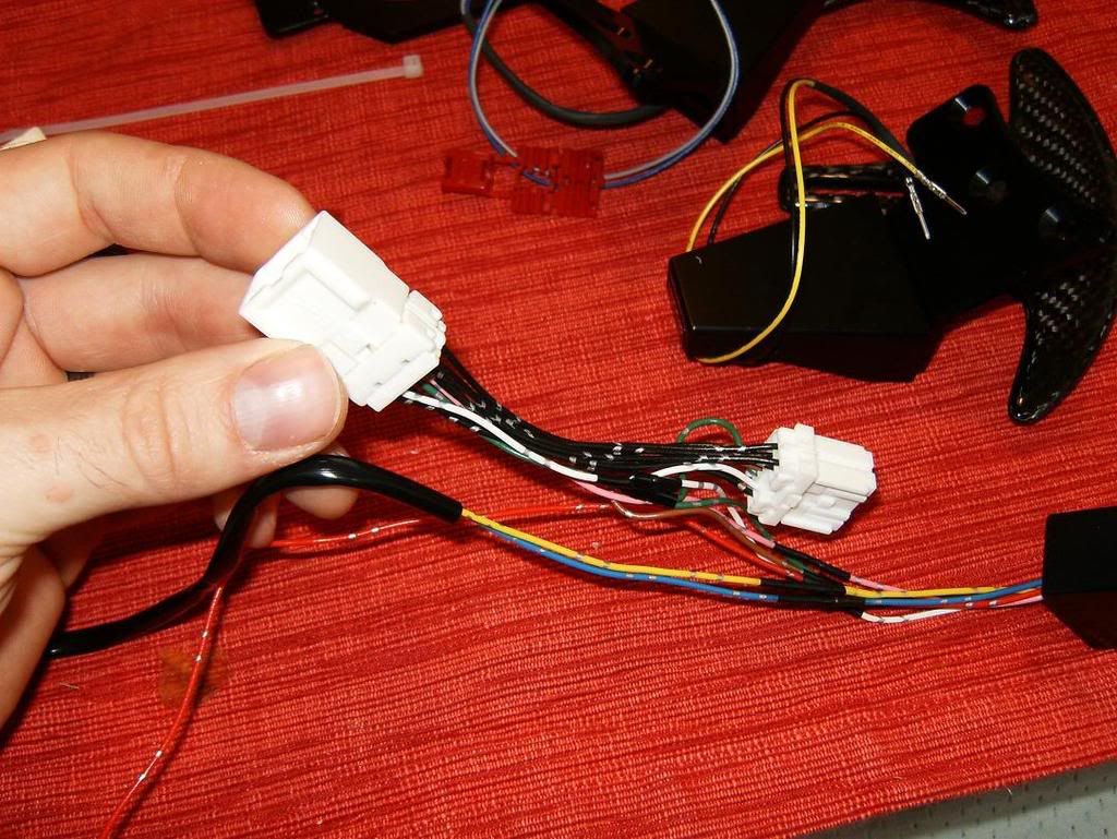
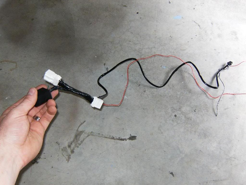
The brains behind the device is an inline harness that locates between the OEM plugs for the shifter.
It would have been nice if they were wrapped, but nothing a little poor man's wrap (electrical tape) can't clean up a tad:
The install was straight forward, and only took about an hour and a half at a beyond leisurely pace.
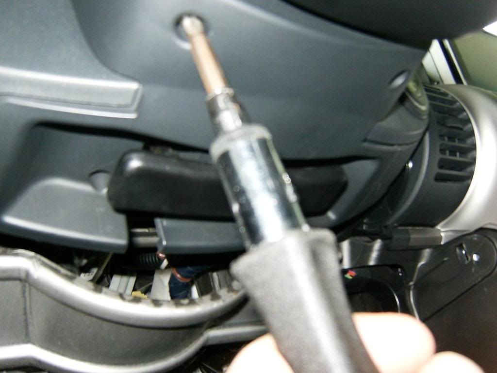
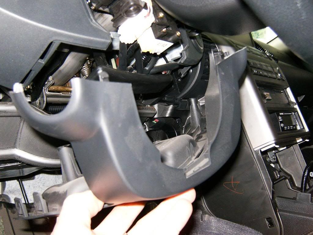
First, I removed the lower steering column cover:
Then I disassemble the center console:
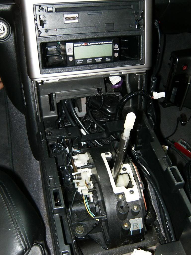
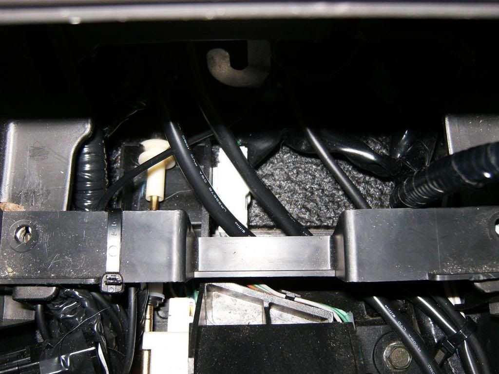
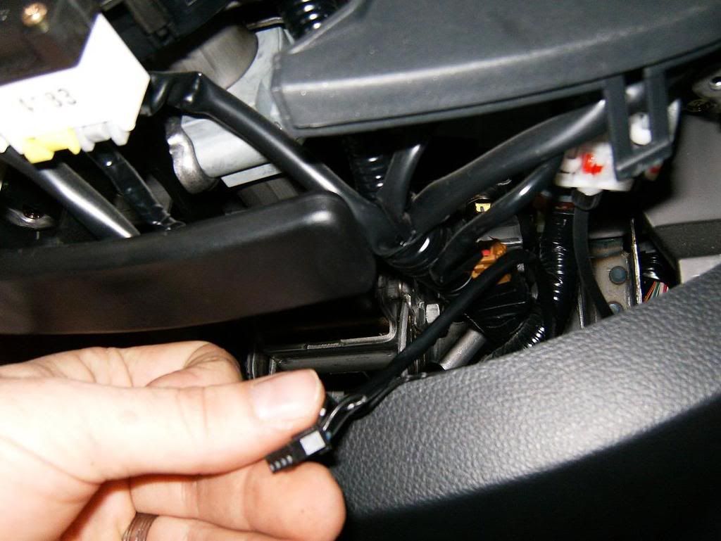
and locate the harness between the OEM shifter and the front of the vehicle.
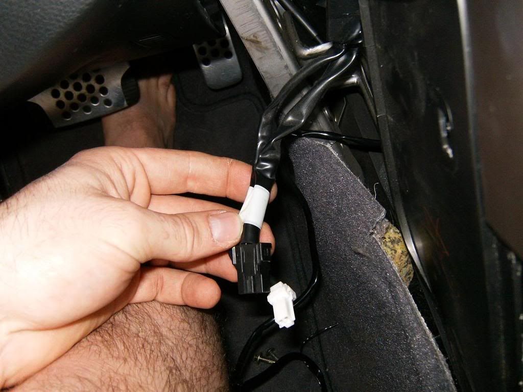
Disconnect it and connect the new inline harness, sorry, I didn't take a picture of the wire harness in. I ran the plug up behind the scuff panel and under the steering column.
It requires a 12V source and ground, so I tapped the power lead from the cigar lighter, and found a ground under the steering column. They include two of those clamp on type wire taps, I didn't take pictures of the one I used for the 12V, and I connected a fork connector to the ground. (Oh yeah, my battery was disconnected.) I didn't take pictures of them though.
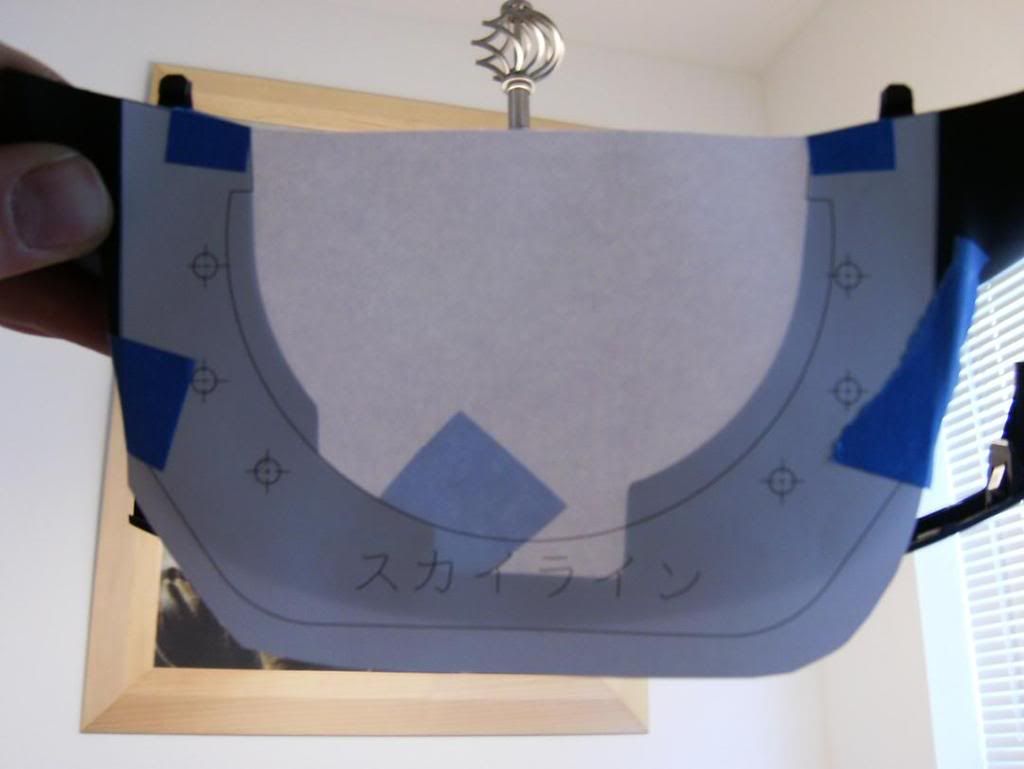
Next I went inside and used the included template and taped it to the lower cover:
Using the marks, I marked the holes for drilling:
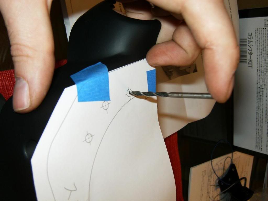
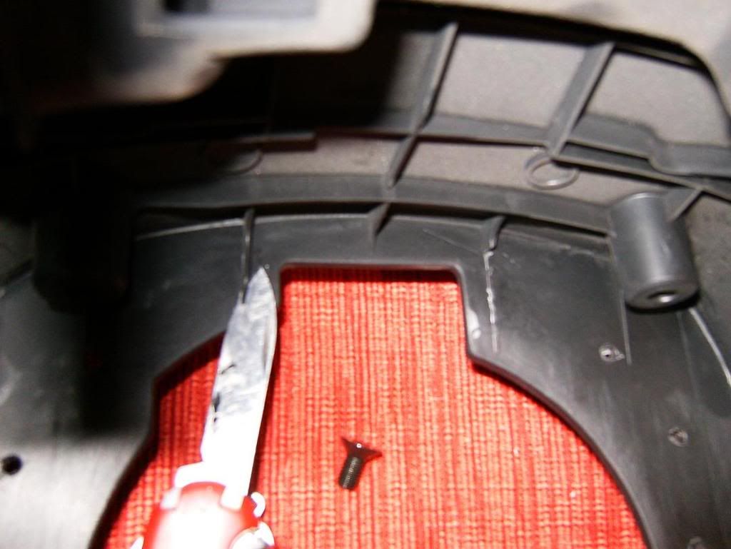
And cut off the unnecessary plastic reinforcements:
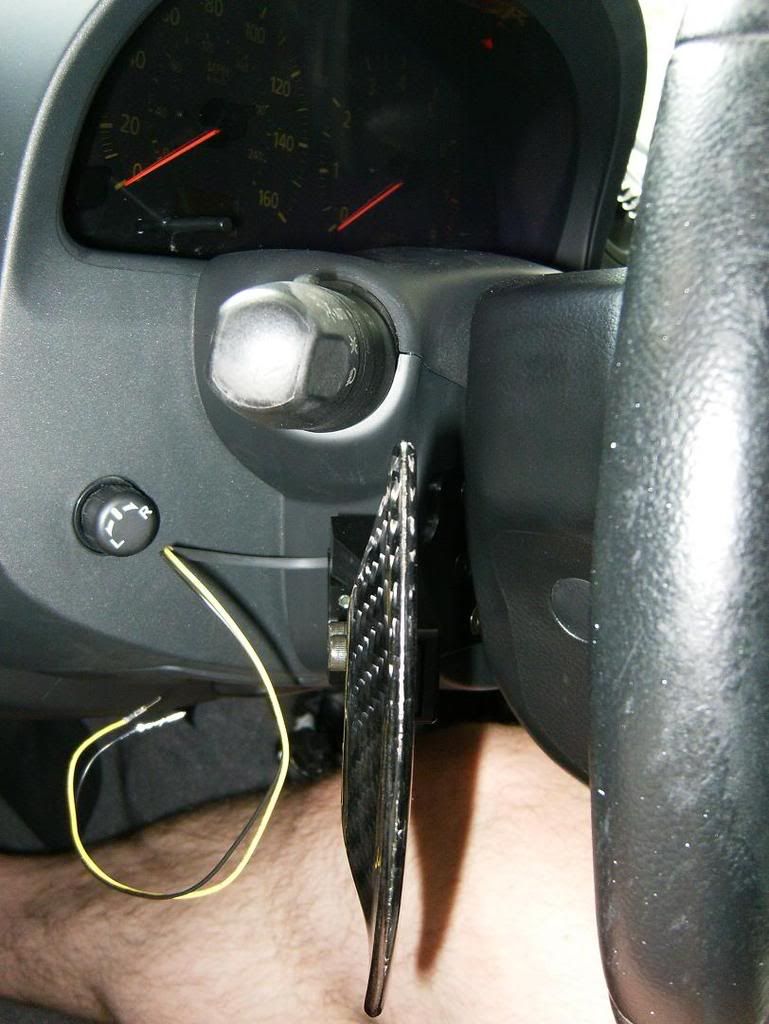
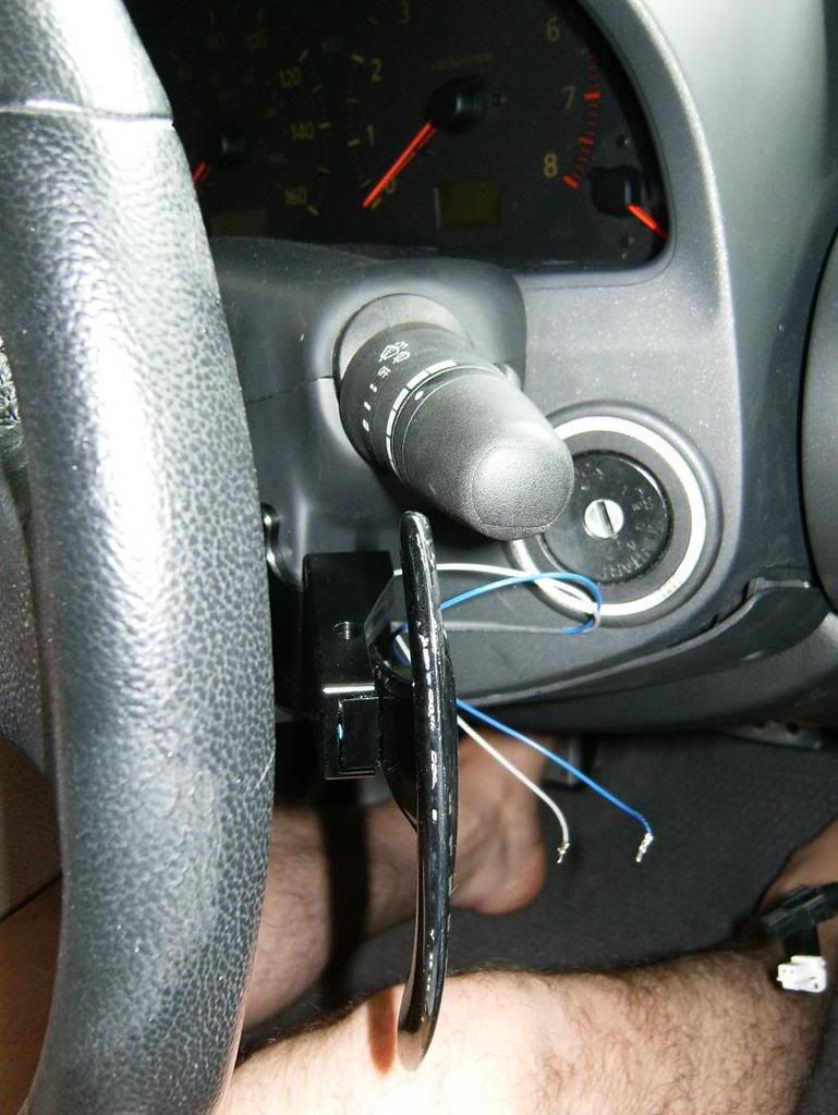
I loosely attached the switch assemblies and CF paddles and ran out to the car for a test fit. I figured where I wanted the switch assemblies to be as well as how far out the paddles were. The paddle width is easily adjustable later on, but it will be more of a pain to adjust the height/twist once it's installed since the screws will be much less accessible. As you can see, I put both stalks in their lowest position to make sure they cleared the paddles.
After the test fit, I removed the switch housings and tightened down the set screws to hold them where I wanted them. I drilled two holes for the wires on the sides of the housing:
Next I reassembled everything. It was easy to fish the wires through the holes after attaching the switch housings to the main support bracket. Now is when I needed the color coded diagram for the plug. (See above.) This plug conveniently sticks into the other wire that was run earlier. I used the included wire clamps to clean up the wires in the lower cover:
*****EDIT***** Be sure and run the wires like this, between the screw posts and the outside edge (it's done on the left in this picture). I'm not sure what the directions say, but Logan is going to make sure they show the wires like this. Otherwise you risk rubbing a wiring harness behind the wheel and potentially throwing some CELs. See my later post describing how to fix this IF YOU ALREADY HAVE THE PROBLEM. If not, just continue on with the wires like so, and you'll be sittin' pretty right off the bat.
And finally had everything ready to go back in the car:
It was as simple as clicking the final plug and putting all the panels back, and we were ready for a test drive!

So far they work just as well as the console shifter, only I don't have to take my hands off the wheel.
Anyway, it's off to Grand Turismo 5 land:
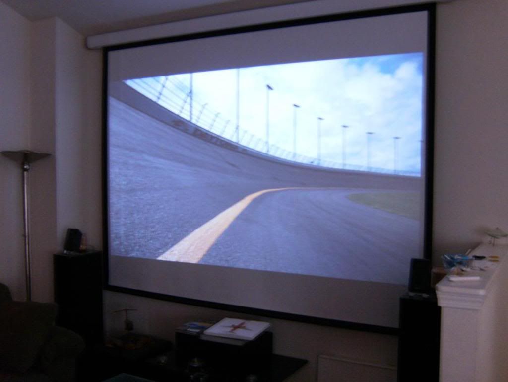
with
. . .so I can at least drive a pretend manual. lol@me

Thanks for lookin! I'll probably edit this some when I'm not so tired.
I was worried that they'd be too low for a 9-3 grip on the steering wheel, but they line up nicely with my pinky/ring fingers and don't feel intrusive. The pull is very minimal, and the shifts are indeed as fast as using the shifter ****. (I'll try and mess with videos later.) Even with mild turning, I found it's easy to access the paddles. You can adjust them to be much higher, but they will interfere with the turn stalk and wiper stalk (if turning left, or with the wipers on max). Also, if you really demand higher/closer paddles, it would be fairly easy to machine your own brackets with the switch housings further forward and higher up. Personally, I thought I was going to mess with making my own CF paddles, but I'm in no rush for now.
The box came wrapped nicely, with each individual part/assembly in its out sealed wrapping.
They even threw in a key chain with the stickers.
The guys at ASpec translated the instructions from Japanese and included the directions with their own install pictures (from a G35) for my G35.
The one item that made the install take 2 minutes longer (yes, 2 minutes
) was the translated instructions were in black and white, and theres one point where you have to pin up a connector (really easy) and it made figuring out which wires go where more difficult. However, given that the Japanese instructions were also included and had colored steps, I simply referred to that diagram, and voila, good to go!Now, onto the parts:
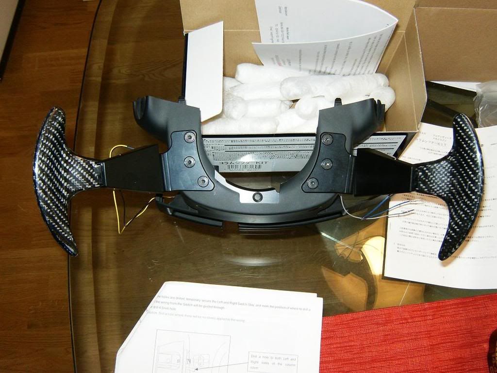
The switch housings and brackets are made out of black metal and have adjustments for raising and lowering, as well as twisting.
The paddles themselves have a glassy feel to them, but are CF.
The brains behind the device is an inline harness that locates between the OEM plugs for the shifter.
It would have been nice if they were wrapped, but nothing a little poor man's wrap (electrical tape) can't clean up a tad:
The install was straight forward, and only took about an hour and a half at a beyond leisurely pace.
First, I removed the lower steering column cover:
Then I disassemble the center console:
and locate the harness between the OEM shifter and the front of the vehicle.
Disconnect it and connect the new inline harness, sorry, I didn't take a picture of the wire harness in. I ran the plug up behind the scuff panel and under the steering column.
It requires a 12V source and ground, so I tapped the power lead from the cigar lighter, and found a ground under the steering column. They include two of those clamp on type wire taps, I didn't take pictures of the one I used for the 12V, and I connected a fork connector to the ground. (Oh yeah, my battery was disconnected.) I didn't take pictures of them though.
Next I went inside and used the included template and taped it to the lower cover:
Using the marks, I marked the holes for drilling:
And cut off the unnecessary plastic reinforcements:
I loosely attached the switch assemblies and CF paddles and ran out to the car for a test fit. I figured where I wanted the switch assemblies to be as well as how far out the paddles were. The paddle width is easily adjustable later on, but it will be more of a pain to adjust the height/twist once it's installed since the screws will be much less accessible. As you can see, I put both stalks in their lowest position to make sure they cleared the paddles.
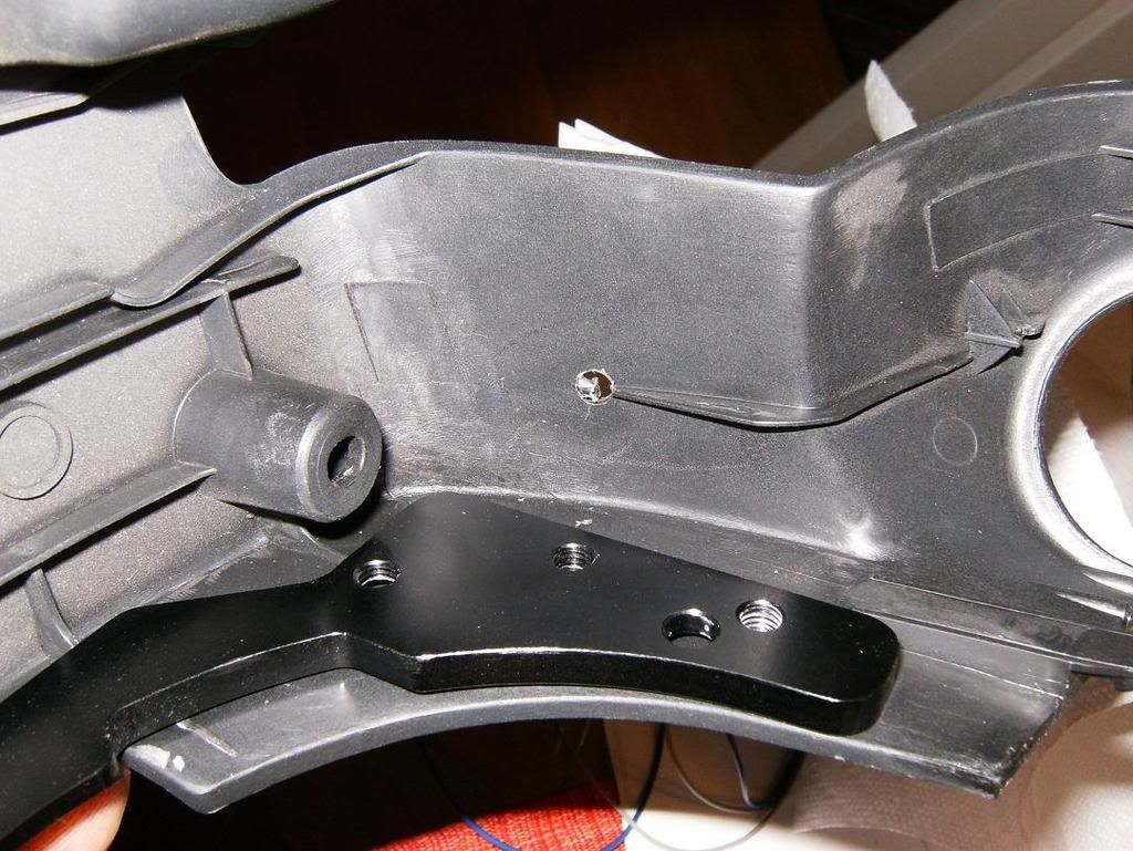
After the test fit, I removed the switch housings and tightened down the set screws to hold them where I wanted them. I drilled two holes for the wires on the sides of the housing:
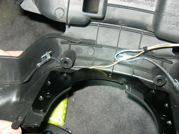
Next I reassembled everything. It was easy to fish the wires through the holes after attaching the switch housings to the main support bracket. Now is when I needed the color coded diagram for the plug. (See above.) This plug conveniently sticks into the other wire that was run earlier. I used the included wire clamps to clean up the wires in the lower cover:
*****EDIT***** Be sure and run the wires like this, between the screw posts and the outside edge (it's done on the left in this picture). I'm not sure what the directions say, but Logan is going to make sure they show the wires like this. Otherwise you risk rubbing a wiring harness behind the wheel and potentially throwing some CELs. See my later post describing how to fix this IF YOU ALREADY HAVE THE PROBLEM. If not, just continue on with the wires like so, and you'll be sittin' pretty right off the bat.
And finally had everything ready to go back in the car:
It was as simple as clicking the final plug and putting all the panels back, and we were ready for a test drive!
So far they work just as well as the console shifter, only I don't have to take my hands off the wheel.
Anyway, it's off to Grand Turismo 5 land:
with
. . .so I can at least drive a pretend manual. lol@me
Thanks for lookin! I'll probably edit this some when I'm not so tired.
Last edited by Drewer; Aug 1, 2008 at 04:07 PM.


Joined: May 2003
Posts: 1,820
Likes: 3
From: Warshington
Originally Posted by FlSHRFun

LOL! How much did this set-up cost?
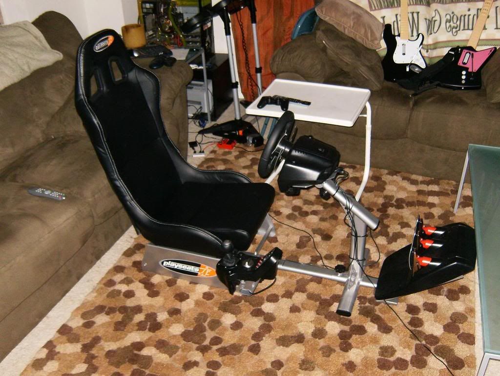
Playseat Evolution: $250 shipped
Logitech G25 (works with PC games too, like GTR:2 and the like) $200 shipped
PS3: $499 for Metal Gear Solid 80GB deal
GT5P $39 at worst buy.
Mrs. Drewer wanted Rock Band, so we got that and I got GT5:P.
We had to stimulate the economy somehow.

PM me if you want to know specific stores for anything in this thread, since I've seen lotsa posts deleted for "promoting non-forum sponsor."


Trending Topics
Originally Posted by Deftronix
Can we please have details on where to get one of these kits?? I have an AT and would prefer this to the oem nissan ones. Looks great!
I have an AT and would prefer this to the oem nissan ones. Looks great!
Originally Posted by SDGeneralCounsel
OEM Nissan, good luck. You can order this kit from ASPEC.
 . I believe zackt69 (rarejdm) can get the oem ones, but your right, I think there is a huge shortage right now on them.


Joined: May 2003
Posts: 1,820
Likes: 3
From: Warshington
Originally Posted by Jeff92se
Price? Looks great. So you pin up one connector, wire a hot and ground and the electricals are plug and play? Nice. So you keep the regular mm also right?
Edit: Yes, this is what was happening, but not with the steering angle sensor. I'll post up pics/fix later.
Originally Posted by Ferrarimanic360
clean your steering wheel!!!
I need to. . .any recommended products?
Last edited by Drewer; Jul 31, 2008 at 02:04 PM.