
No more JDM finisher gap with double din: pics inside


Joined: Sep 2003
Posts: 511
Likes: 0
From: Chicago, IL
No more JDM finisher gap with double din: pics inside
Yeah, sorry, but I thought that "window foam" didn't quite cut it, and I wanted a more OEM appearance.
Here are the pics, if anyone cares how I did it, I'd be happy to post a DIY, otherwise, have a nice day.

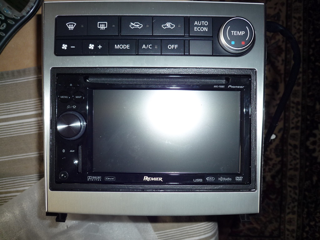


Here are the pics, if anyone cares how I did it, I'd be happy to post a DIY, otherwise, have a nice day.


Joined: Sep 2003
Posts: 511
Likes: 0
From: Chicago, IL
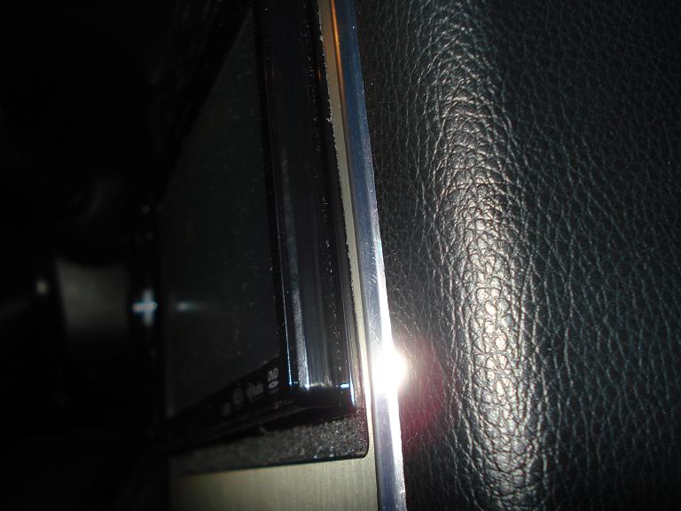
My gap is no bigger than yours -- i chose not to have the F90bt stick out 1/2 or 1/4" -- looks weird. -- you probably advanced the f90bt forward until the sides of the step off were flush with the JDM finisher -- then you pushed the f90bt all the way down...
then you had a gap at the top.
Not my style -- i wanted it flush to keep it more OEM appearing.
then you had a gap at the top.
Not my style -- i wanted it flush to keep it more OEM appearing.

Joined: Sep 2003
Posts: 511
Likes: 0
From: Chicago, IL
thanks --
I used a scosche ddin trim ring ($9.99 on ebay and various other e-stores), made a cardboard template of the JDM opening, then cut the trim down to size with an exacto knife and metal ruler.
After a little sanding with 1000 grit, clear epoxy and adding small rectangular spacers (outta the excess ABS plastic) to keep the unit flush .. I used a flat black latex paint and finished it off. I have a bit more painting to do to get rid of the "line" at the bottom of the trim ring, but it works much better for me than the other alternatives.
Trending Topics

Joined: Sep 2003
Posts: 511
Likes: 0
From: Chicago, IL
You use your stock bracket, yes.
You do have to do some drilling of the stock bracket to get your holes to line up, because if you used the stock holes into the aftermarket DDin unit, your stereo would stick out about 1/2" and be perfectly centered (vertically) -- not cool.
You do have to do some drilling of the stock bracket to get your holes to line up, because if you used the stock holes into the aftermarket DDin unit, your stereo would stick out about 1/2" and be perfectly centered (vertically) -- not cool.

Joined: Sep 2003
Posts: 511
Likes: 0
From: Chicago, IL
This is the ring I implemented:

Here's an example of another members F series sticking out with the "window foam" underneath...
Now if you want, obviously you can paint the trim ring any color, piano black, etc to match the DDin unit. i used a foam brush and flat black so it would match the color of the inside lining of the JDM DDin opening.
Last edited by PeterUbers; Mar 28, 2009 at 05:33 PM.
I'm thinking of making my F90bt flush like yours.. great info.
But i got a question for you, sorry to change the subject.
I hear a static sound on 0 volume, what can the problem be? I used the 7550 metra harness. Can a bad ground cause this? I grounded it to the bracket.
thanks
But i got a question for you, sorry to change the subject.
I hear a static sound on 0 volume, what can the problem be? I used the 7550 metra harness. Can a bad ground cause this? I grounded it to the bracket.
thanks
Joined: Sep 2003
Posts: 511
Likes: 0
From: Chicago, IL
Jin -- unfortunately -- in my epic reading of all the thousands of posts regarding 7550 vs. 7551 and all that, it seems that both harnesses have their pro's and con's. I always ground to the chassis:
I took the back ground off the Pioneer harness and soldered (i solder all my wire joints) a heavy guage (10 gauge) wire and ran it to the firewall where there are a few BIG bolts that attach various things -- then I uses a very large O-ring type adapter and soldered the end of the ground wire to this and hooked this to one of the bolts -- excellent ground connection.
The other thing I did was move all my speaker RCA's (i have the 7551) away from the power wires (ACC, BATT, GROUND) with zip ties in order to insulate them from the RF interference produced by the current in the wires running high current.
Lemme know if that all works -- did you solder your wire connections?
Does the static sound go away when you increase the volume in small increments?
The last resort I would recommend is to purchase Black betty's grounding kit if you don't have that already -- to improve the overall grounds of the engine and thus help relieve your system of interference. I have some testing to do and I'll get back to you with my own results.
Last edited by PeterUbers; Mar 29, 2009 at 11:48 AM.
