
DIY guide: KPtechnology Mirror tilt down module ...plus video


DIY guide: KPtechnology Mirror tilt down module ...plus video
Use this guide at your own risk. I am not responsible for any errors you have caused. If you have any questions regarding beyond this DIY please post on this thread and KPtechnologies will reply as soon as they can. If you catch an error on this DIY, please let me know so I can correct the error. Thanks.
Before install note:
If you have other KPtechnologies unit, you can connect the red (12volt constant) and yellow wire (12v ignition power) to the same location as your other units. If you don't, follow the guide for the yellow and red wire.
1) Red wire (12v constant) remove the plug by pressing the two clips on the side for wiring simplicity on the BCM. Connect the red wire to the 12v constant wire pictured below. (BCM plug)
2) Yellow wire (12v ignition power) I use a wire end spade like this one.gif) and used one of the empty slots on the fuse box.
and used one of the empty slots on the fuse box.
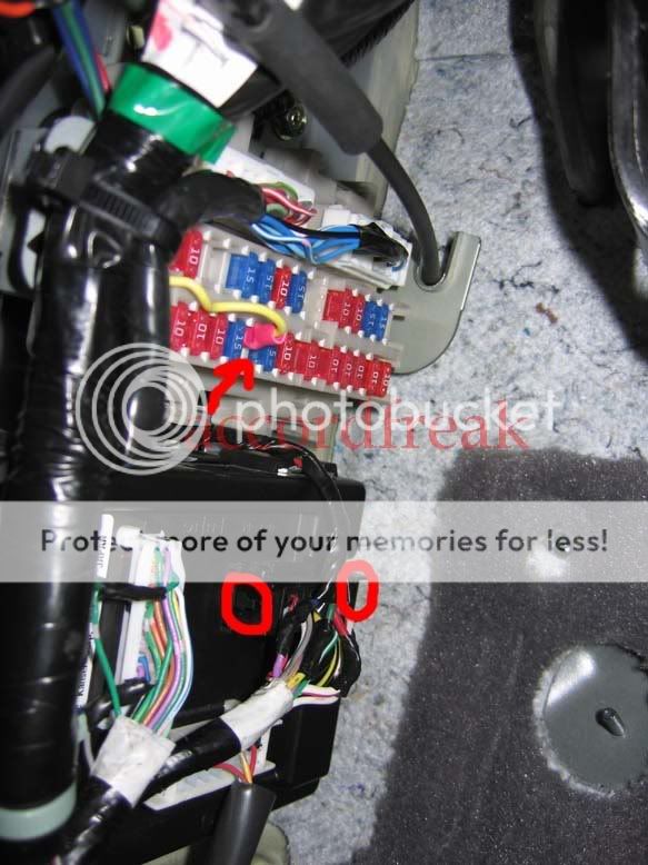

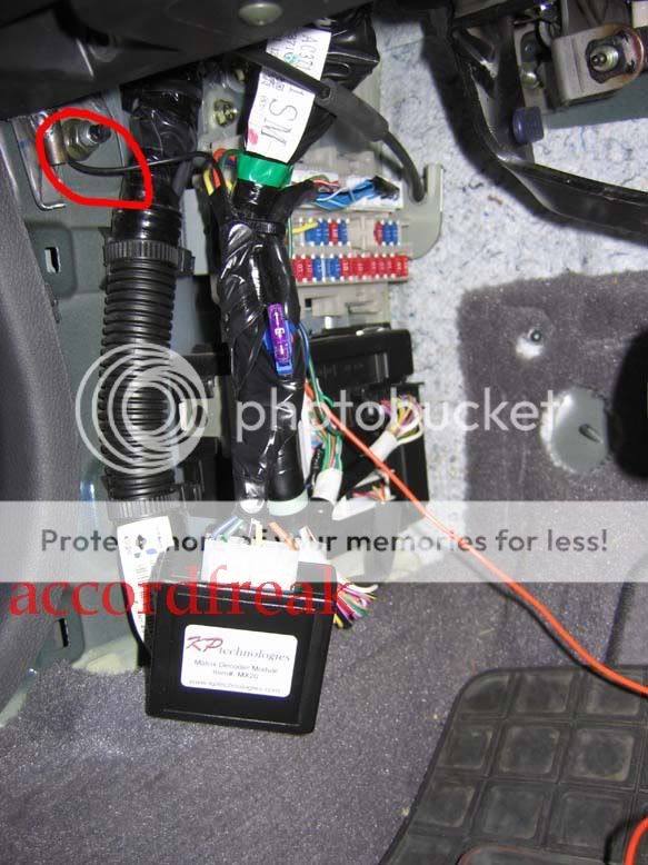
3) Black Wire- connect the ground wire. I used the ground point pictured below for all my KP modules.
4) Purple wire- reverse input- This wire is located on the passenger side under the glove box. (you have to remove your glove box.) The reverse input wire is located on the white box as shown below. You have to unbolt the 10mm bolt and lift the white box upwards and out to free it from the bracket. (see below)

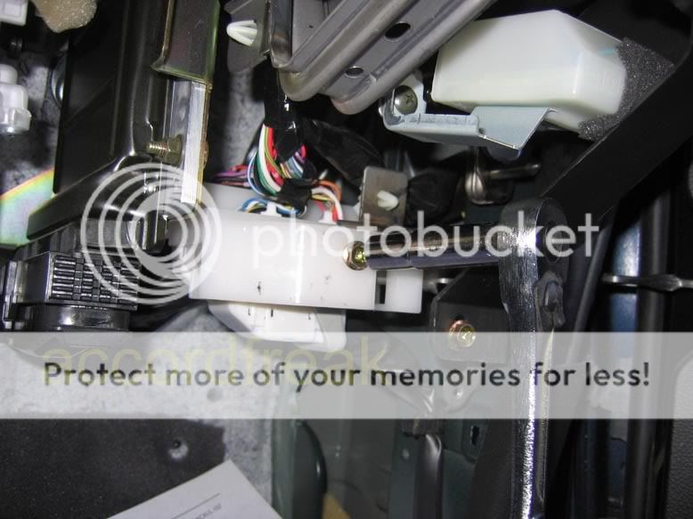
The reverse wire to be tapped.


5)Remove the lower panel plastic on the driverside and located/remove the plug on the mirror switch

6) cut the yellow and red/white wire. Make sure you have enough slack to solder or crimp connections
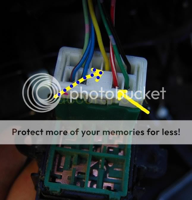
7) Blue wire (mirror up output)
Once the yellow wire has been cut. Solder or butt together the blue wire with the yellow wire (MIRROR side)
8) green wire (mirror up input)
Solder or butt together the green wire with the other cut yellow wire (SWITCH SIDE)
9) Brown wire ( mirror down output)
Once the red/white wire has been cut. Solder or butt together the brown wire with the cut red/white wire (MIRROR side)
10) Orange (mirrow down input)
Solder or butt together the ORANGE wire with the other cut red/white wire (SWITCH SIDE)
here's the general idea of what it should look.

follow the programming instructions and you're set! Mine is set on MODE 2. so I have to put it in reverse twice for it to tilt. Mode 1 lets you tilt the 1st time you put it in reverse.
here's the video: (ignore the beep, it's from the stock navi)

Before install note:
If you have other KPtechnologies unit, you can connect the red (12volt constant) and yellow wire (12v ignition power) to the same location as your other units. If you don't, follow the guide for the yellow and red wire.
1) Red wire (12v constant) remove the plug by pressing the two clips on the side for wiring simplicity on the BCM. Connect the red wire to the 12v constant wire pictured below. (BCM plug)
2) Yellow wire (12v ignition power) I use a wire end spade like this one
and used one of the empty slots on the fuse box.3) Black Wire- connect the ground wire. I used the ground point pictured below for all my KP modules.
4) Purple wire- reverse input- This wire is located on the passenger side under the glove box. (you have to remove your glove box.) The reverse input wire is located on the white box as shown below. You have to unbolt the 10mm bolt and lift the white box upwards and out to free it from the bracket. (see below)
The reverse wire to be tapped.
5)Remove the lower panel plastic on the driverside and located/remove the plug on the mirror switch
6) cut the yellow and red/white wire. Make sure you have enough slack to solder or crimp connections
7) Blue wire (mirror up output)
Once the yellow wire has been cut. Solder or butt together the blue wire with the yellow wire (MIRROR side)
8) green wire (mirror up input)
Solder or butt together the green wire with the other cut yellow wire (SWITCH SIDE)
9) Brown wire ( mirror down output)
Once the red/white wire has been cut. Solder or butt together the brown wire with the cut red/white wire (MIRROR side)
10) Orange (mirrow down input)
Solder or butt together the ORANGE wire with the other cut red/white wire (SWITCH SIDE)
here's the general idea of what it should look.
follow the programming instructions and you're set! Mine is set on MODE 2. so I have to put it in reverse twice for it to tilt. Mode 1 lets you tilt the 1st time you put it in reverse.
here's the video: (ignore the beep, it's from the stock navi)
Last edited by accordfreak; May 16, 2007 at 01:15 PM.


Thats cool. They make some great stuff. It would be nice if they could combine all or most of their diffrent products into one Module, like a alarm module. That way you don't have so many diffrent modules in the car. I would get this, the keyless entry beep, and the sunroof mod. If they were combined into one unit.

Originally Posted by Konazo
Thats cool. They make some great stuff. It would be nice if they could combine all or most of their diffrent products into one Module, like a alarm module. That way you don't have so many diffrent modules in the car. I would get this, the keyless entry beep, and the sunroof mod. If they were combined into one unit.


Trending Topics
No, it is not availible yet. We will be ordering the parts this week, so they will be ready in 2-3 weeks, if all goes well.
It would be very difficult to combine modules in to one 'super module' that only has the features people want, because everyone wants different things. Also, certain modules, like the remote sunroof module, only works with certain cars (G35 coupes), so sedan people would pay for features they wouldn't even be able to use.
It would be very difficult to combine modules in to one 'super module' that only has the features people want, because everyone wants different things. Also, certain modules, like the remote sunroof module, only works with certain cars (G35 coupes), so sedan people would pay for features they wouldn't even be able to use.


Thanks for posting up this DIY! 
I followed this thread, Retzius' thread, and the DIY on KP Technologies' site to wire up a single module in my 2005 5AT coupe:
Red Wire - I connected the red wire to the #55 (red/white) wire on the BCM
Yellow Wire - I tapped the white/blue wire in the harness per the official DIY. Note, there are 2 white/blue wires in the harness- tap the thicker one.
Black Wire - Used the ground point per Accordfreak's / Retzius' DIYs. I didn't see a need to mess around with the VDC ground since the other point was easily accessible.
Purple Wire - I tapped the wire harness on the driver's side per this DIY and the official writeup on KP's site. There were 3 purple wires - one twisted together with an orange wire, one towards the pedals, and one kinda hidden in the back towards the door (this is the wire you need and its pretty close to where you see it in the picture).
Mirror Wires - Same as all of the DIY's. Its a real b!tch to get the harness free because its a tight space, the release is small, and the plastic tie is hard to cut. Just take your time.
Thanks again guys!

Thread
Thread Starter
Forum
Replies
Last Post
RemmyZero
V36 DIY
10
Apr 23, 2018 11:13 AM