
MOD Project: Infiniti G35 MacMini


Thread Starter
|
Registered User
Joined: Oct 2006
Posts: 22
Likes: 0
MOD Project: Infiniti G35 MacMini
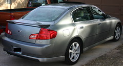
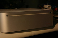
The victim:

...place holder for project goals, ect...
(when I get unlazy to actually document the plans I have in my head)
Stock pictures... before the install:


...place holder for project goals, ect...
(when I get unlazy to actually document the plans I have in my head)
Stock pictures... before the install:
Last edited by Zitt; Mar 2, 2007 at 06:30 PM. Reason: Adding Victim pics
Thread Starter
|
Registered User
Joined: Oct 2006
Posts: 22
Likes: 0
Infiniti G35 Carputer mac mini led mod
The stock Intel Mac Mini has a white Power LED. Because I want the mac mini to look "stock" and right at home in my G35's dash; I'm going to spell out the details on how to mod your mac mini's stock LED color.
After many google search attempts; I have not seen anyone publish a tutorial on how to change the color of the LED in your mini. I hope the Mini Modder's enjoy this how-to.
Please keep in mind that you take all responsibility for implementing the LED mod on your Mac Mini. It will void your warranty so keep this in mind BEFORE attempting this mod. Neither Zittware nor WizD is liable for voiding your warranty.
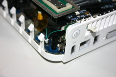
First you need to dissemble your mac mini to get access to the white LED.
I did this by following two tutorials:
First being the disassembly video @ Smash's world. I elected to use the putty knife method instead of the wire method. The putty knife seemed like less effort despite the risk of scratching the mini's body. I used a Warner 1/2" Flex putty knife purchased from lowes. It had the thinest profile of all putty knifes at Lowes.
Once I had the top cover off my mini; I began carefully disassembling the mini using applefritter.com's step-by-step guide.
I stopped before removing the ram or the hard drive.
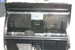
You need to remove the black tray assembly containing the cdrom and HD; but do not need to remove the CPU or Ram from the motherboard.
After many google search attempts; I have not seen anyone publish a tutorial on how to change the color of the LED in your mini. I hope the Mini Modder's enjoy this how-to.
Please keep in mind that you take all responsibility for implementing the LED mod on your Mac Mini. It will void your warranty so keep this in mind BEFORE attempting this mod. Neither Zittware nor WizD is liable for voiding your warranty.
First you need to dissemble your mac mini to get access to the white LED.
I did this by following two tutorials:
First being the disassembly video @ Smash's world. I elected to use the putty knife method instead of the wire method. The putty knife seemed like less effort despite the risk of scratching the mini's body. I used a Warner 1/2" Flex putty knife purchased from lowes. It had the thinest profile of all putty knifes at Lowes.
Once I had the top cover off my mini; I began carefully disassembling the mini using applefritter.com's step-by-step guide.
I stopped before removing the ram or the hard drive.
You need to remove the black tray assembly containing the cdrom and HD; but do not need to remove the CPU or Ram from the motherboard.
Thread Starter
|
Registered User
Joined: Oct 2006
Posts: 22
Likes: 0
Now the real fun begins. 
Let's mod the MacMini power LED:
Materials needed:
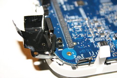
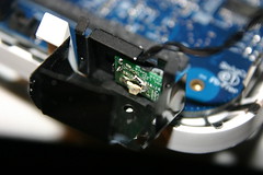
Remove the white LED's mini circuit board by gently pulling the black hard tape apart at the rear of the assembly. I used a hobby knife to start removing the tape. Be gentle; the black tape easily rips despite being thick.
Once the tape is free; you'll have a small circuit board double sticky taped to the back of the black housing. Use that same knife to gently pry the circuit board from the tape.
Take care with the wires attaching to this board. They are fragile and will break easily.
2) Mac Mini's LED circuit board w/ "foam" light blocker
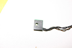
Here's a picture of the circuit board removed. The black foam is adhesive backed; which is how it attaches to the circuit board.
I beleive the purpose of this foam is to provide a spacer to secure the circuit board in the assembly... maybe to prevent "rattle". Apple certainly knows how to spec quality assemblies.
Gently remove the adhesive foam using a hobby knife. Take care to remove with the adhesive intact on the foam (not circuit board) so you can reuse it during reassembly.
3) Desoldering time
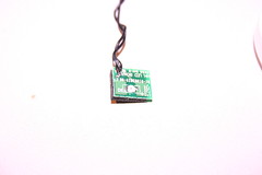
Notice the white diode labeled D1. and the plus (+) symbol.
Using an SMT tip; desolder the diode at D1 using a solder braid.
Clean up the diode pads using solder braid.
Rotate the wires by to the backside of the circuit board; one at a time; to ensure you don't accidently wire the board / LED backwards. I used a solder braid to remove the solder; then resoldered on the non component (or non copper) side.
4) MacMini's HH LED prep
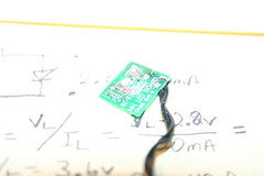
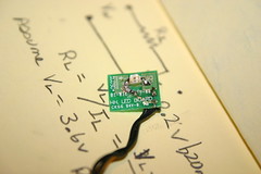
Using the hobby knife; scrape off enough solder mask to mount your desired color. The author used a 1206 SMT LED - Orange from Digikey - A Stanley AA1101W.
For our calcuations; we are going to assume the forward drop of the stock white LED is a typical 3.6V. Assume typical LED currents of ~20mA.
Since we are using a lower voltage LED; we need to put a current limiting resistor (RLED) into the circuit to "drop" some voltage. Using some electrical engineering - Kirchhoff's voltage law
http://en.wikipedia.org/wiki/Kirchhoff's_circuit_laws#Kirchhoff.27s_voltage_law
; we know that the sum of all voltage must be zero.
0 = Vwhite + Vr.led + Vled
or
(a) Vrled = Vwhite - Vled
Kirchhoff's current law
http://en.wikipedia.org/wiki/Kirchhoff's_circuit_laws#Kirchhoff.27s_current_law
we know that the current through our LED must be equal to the current through our new resistor RLED.
(b) Ir.led = I.led = 20mA
Using Ohm's Law http://en.wikipedia.org/wiki/Ohm's_law
we can solve for the value of RLED:
I = V/R ; solving for R
R = V/I
RLED = Vrled / Ir.led ; knowing (a) and (b) yields:
RLED = ( Vwhite - Vled ) / ( I.led )
From our new LED's datasheet we know that VLED = 2.2V; so:
RLED = ( 3.6V - 2.2V ) / ( 20mA) = 70 ohms
The closest resistor value the author had in 604 package was 56ohms; so we will use 56ohms in the remaining steps.
NOTE: If you are going to replace the LED with a newer color like Blue, bright green, or uv... note that the forward voltage of these LEDs is closer to the original White LED. As such; you will *NOT* cut the traces below or solder in a 56ohm resistor as calcuated above. IF IN DOUBT; check your datasheet for it's typical forward drop @ 20mA.
IF your using a standard low voltage LED (red, yellow, orange) with a Vdrop ~2.2V continue. Else skip the next step cutting the trace below.
Cut the long trace on the Kathode (+) side of the LED. Make the cut wide enough to fit a 604 SMT resistor.
Let's mod the MacMini power LED:
Materials needed:
- High End SMT (surface mount technology) capable soldering with fine SMT tip
- desoldering wick
- SMT 1206 LED color of your choice
- Datasheet for the LED you selected. Need forward voltage drop spec @ 20mA.
- SMT 604 resistor @ 56ohms.
- hobby knife with newish triangle blade.
- solder
- uber soldering skillz for SMT devices
Remove the white LED's mini circuit board by gently pulling the black hard tape apart at the rear of the assembly. I used a hobby knife to start removing the tape. Be gentle; the black tape easily rips despite being thick.
Once the tape is free; you'll have a small circuit board double sticky taped to the back of the black housing. Use that same knife to gently pry the circuit board from the tape.
Take care with the wires attaching to this board. They are fragile and will break easily.
2) Mac Mini's LED circuit board w/ "foam" light blocker
Here's a picture of the circuit board removed. The black foam is adhesive backed; which is how it attaches to the circuit board.
I beleive the purpose of this foam is to provide a spacer to secure the circuit board in the assembly... maybe to prevent "rattle". Apple certainly knows how to spec quality assemblies.
Gently remove the adhesive foam using a hobby knife. Take care to remove with the adhesive intact on the foam (not circuit board) so you can reuse it during reassembly.
3) Desoldering time
Notice the white diode labeled D1. and the plus (+) symbol.
Using an SMT tip; desolder the diode at D1 using a solder braid.
Clean up the diode pads using solder braid.
Rotate the wires by to the backside of the circuit board; one at a time; to ensure you don't accidently wire the board / LED backwards. I used a solder braid to remove the solder; then resoldered on the non component (or non copper) side.
4) MacMini's HH LED prep
Using the hobby knife; scrape off enough solder mask to mount your desired color. The author used a 1206 SMT LED - Orange from Digikey - A Stanley AA1101W.
For our calcuations; we are going to assume the forward drop of the stock white LED is a typical 3.6V. Assume typical LED currents of ~20mA.
Since we are using a lower voltage LED; we need to put a current limiting resistor (RLED) into the circuit to "drop" some voltage. Using some electrical engineering - Kirchhoff's voltage law
http://en.wikipedia.org/wiki/Kirchhoff's_circuit_laws#Kirchhoff.27s_voltage_law
; we know that the sum of all voltage must be zero.
0 = Vwhite + Vr.led + Vled
or
(a) Vrled = Vwhite - Vled
Kirchhoff's current law
http://en.wikipedia.org/wiki/Kirchhoff's_circuit_laws#Kirchhoff.27s_current_law
we know that the current through our LED must be equal to the current through our new resistor RLED.
(b) Ir.led = I.led = 20mA
Using Ohm's Law http://en.wikipedia.org/wiki/Ohm's_law
we can solve for the value of RLED:
I = V/R ; solving for R
R = V/I
RLED = Vrled / Ir.led ; knowing (a) and (b) yields:
RLED = ( Vwhite - Vled ) / ( I.led )
From our new LED's datasheet we know that VLED = 2.2V; so:
RLED = ( 3.6V - 2.2V ) / ( 20mA) = 70 ohms
The closest resistor value the author had in 604 package was 56ohms; so we will use 56ohms in the remaining steps.
NOTE: If you are going to replace the LED with a newer color like Blue, bright green, or uv... note that the forward voltage of these LEDs is closer to the original White LED. As such; you will *NOT* cut the traces below or solder in a 56ohm resistor as calcuated above. IF IN DOUBT; check your datasheet for it's typical forward drop @ 20mA.
IF your using a standard low voltage LED (red, yellow, orange) with a Vdrop ~2.2V continue. Else skip the next step cutting the trace below.
Cut the long trace on the Kathode (+) side of the LED. Make the cut wide enough to fit a 604 SMT resistor.
Thread Starter
|
Registered User
Joined: Oct 2006
Posts: 22
Likes: 0
5) Mac Mini's HH LED modified
Solder the new 1206 SMT LED to your new landing pads; over the existing hole.
If using a ~2.2V LED; solder your 56ohm 604 smt resistor to the cut trace.
6) Mac Mini's HH LED reinstalled
Reattach the black foam spacer over the new LED - allowing the LED to shine through the hole in the foam.
Reinstall the LED board into it's housing.
Make sure to align the LED to the hole in the black tape.
Gently manuver the LED boards wire out the original hole.
Reassemble the black tape around the modified HH LED board.
7) Reverse your disassembly; returning the mac mini back to it's assembled form. Take care to reassemble everything.
Here's the final look; complete with an Orange power LED which will match nicely with the G35's orange iluminated dash.
Thread Starter
|
Registered User
Joined: Oct 2006
Posts: 22
Likes: 0
Mac Mini Modding: Disabling the internal speaker
Lots of work has been done behind the scenes to test the mac mini before the G35 is disassembled for installation... here's some of the highlights.
Before reassembling the Intel Mac Mini; I finished up some last minute issues.
First; To use the mac mini in my car; It was desirable to disable the internal speaker of the mini. To do this; simply remove J23's connector on the back board which connects to the CDROM. I left this connector taped to the black plastic of the cdrom assembly.

Next; To remote power up the mac mini using the Carnetix CNX-P1900 DC-DC supply; I put the supplied power button "y" adapter and routed the external connector out of the rear fan hole. I later changed this to exit on of the bottom vent holes.
I began wiring the P1900 supply to my test ATX powersupply... with a simulated ignition. No pictures here; but can post a diagram if there is interest. This was done to work out the kinks of the power supply, Mini, and 700TSV lcd before it's installed in the G35.
On tap tomorrow is a trip to Radio Shack to get a DPDT mini switch and a 1/4" audio plug for the continued installation.
Before reassembling the Intel Mac Mini; I finished up some last minute issues.
First; To use the mac mini in my car; It was desirable to disable the internal speaker of the mini. To do this; simply remove J23's connector on the back board which connects to the CDROM. I left this connector taped to the black plastic of the cdrom assembly.
Next; To remote power up the mac mini using the Carnetix CNX-P1900 DC-DC supply; I put the supplied power button "y" adapter and routed the external connector out of the rear fan hole. I later changed this to exit on of the bottom vent holes.
I began wiring the P1900 supply to my test ATX powersupply... with a simulated ignition. No pictures here; but can post a diagram if there is interest. This was done to work out the kinks of the power supply, Mini, and 700TSV lcd before it's installed in the G35.
On tap tomorrow is a trip to Radio Shack to get a DPDT mini switch and a 1/4" audio plug for the continued installation.
Thread Starter
|
Registered User
Joined: Oct 2006
Posts: 22
Likes: 0
It's ALIVE
Austin Modders met at my house this past saturday to begin the task of installing the MacMini into my G35.
After a long weekend... and several nights after work; I'm proud to present that the G35 MacMini project is alive and playing MP3s... dishing out gps coordinates via Google Earth and Earth Bridge.
First a Stock picture... before the install:
And here it is after the install:
http://www.flickr.com/photos/52968060@N00/273618824/Yeap... here's the car when everything put away. still looks stock - which was ONE of the goals of this project.
Bet your thinking: "ok smart ash... wtf are you trying to pull"
 nothing ... I swear!
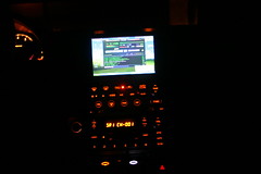
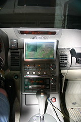
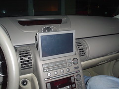
The touch screen is located in the same location as the stock navi screen. Closeup of the MP3Car.com's 700TSV touch screen installed in the center console. Plans are in place to purge the housing of it's brushed aluminum bezel... but you'll have to wait to see that! Later in the project.
http://www.flickr.com/photos/52968060@N00/273618819/Onscreen is Google Earth running Earth Bridge... and Winamp Playing mp3s in the foreground.
Why you might ask? Because MP3Car.com has yet to honor it's $50off coupon for Streetdeck for my September order.
But... Where oh Where is the MacMini?
http://www.flickr.com/photos/52968060@N00/273618818/The same location as the stock Navigation system.
Ofcourse you can see a closeup... you needn't ask!
http://www.flickr.com/photos/52968060@N00/273618820/Macmini installed in the G35's navi cubby uses a DigitalWheelz Din Converter from MP3Car.com. G35 was secured in the DIN converter using #6-32x3/8" standoffs on both sides.
The modified CarNetix CNX-P1900 PSU is mounted on the right side.
The left side is reserved for the USB2.0 hub... to be installed later.
All of this will be polished off with a custom cnced front panel when I get a chance.
More later...
After a long weekend... and several nights after work; I'm proud to present that the G35 MacMini project is alive and playing MP3s... dishing out gps coordinates via Google Earth and Earth Bridge.
First a Stock picture... before the install:
And here it is after the install:
http://www.flickr.com/photos/52968060@N00/273618824/Yeap... here's the car when everything put away. still looks stock - which was ONE of the goals of this project.
Bet your thinking: "ok smart ash... wtf are you trying to pull"
nothing ... I swear!The touch screen is located in the same location as the stock navi screen. Closeup of the MP3Car.com's 700TSV touch screen installed in the center console. Plans are in place to purge the housing of it's brushed aluminum bezel... but you'll have to wait to see that! Later in the project.
http://www.flickr.com/photos/52968060@N00/273618819/Onscreen is Google Earth running Earth Bridge... and Winamp Playing mp3s in the foreground.
Why you might ask? Because MP3Car.com has yet to honor it's $50off coupon for Streetdeck for my September order.
But... Where oh Where is the MacMini?
http://www.flickr.com/photos/52968060@N00/273618818/The same location as the stock Navigation system.
Ofcourse you can see a closeup... you needn't ask!
http://www.flickr.com/photos/52968060@N00/273618820/Macmini installed in the G35's navi cubby uses a DigitalWheelz Din Converter from MP3Car.com. G35 was secured in the DIN converter using #6-32x3/8" standoffs on both sides.
The modified CarNetix CNX-P1900 PSU is mounted on the right side.
The left side is reserved for the USB2.0 hub... to be installed later.
All of this will be polished off with a custom cnced front panel when I get a chance.
More later...
Thread Starter
|
Registered User
Joined: Oct 2006
Posts: 22
Likes: 0
Time to report on the weekend activities.
As I stated in a previous post; one of the goals is to have the g35 look stock when the toys are put away. To this end; it was desirable to mount the override switches in an inconsipucious place. That place: The ashtray.
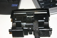
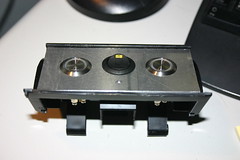
Step one involved removing the ashtray from the g35... which gives us the following stock ashtray:
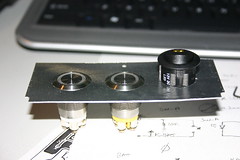
The switches will be Bulgin Vandal resistant switches. Ring type with Amber and White LEDs. The Amber LED Switch will control the PSU via remote powerup on J1 Pin 1 of the PSU. The White will give me access to the MacMini's powerbutton which cannot be reached as it is in the dash.
I also integrated a "kill" switch to remove the PSU / MacMini from car power. IE long trips where the car will set for long periods of time. This switch is a Eswitch rocker switch RR3112 LBLKBLKYEL SPST with a 12VDC Amber LED. It interrupts the battery power to the PSU.
Ofcourse I needed a way to mount these beasties on top of the ash tray; so I went through several revisions to come up with the following design:
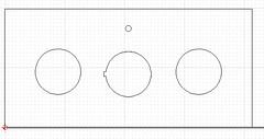
This is the most optimal configuration due to the space contraints inside the G35's ashtray.
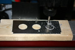
This design was then ported to my CNC where it was cut out of 0.1" Aluminum plate.
Here are some pictures I took of a previous revision while CNCing and test fitting.
G35 Ashtray switch insert (cncing):
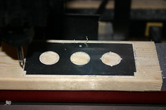
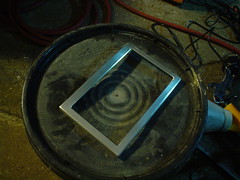
G35 Ashtray switch insert (done):
G35 Ashtray switch insert (test fit):
As I stated in a previous post; one of the goals is to have the g35 look stock when the toys are put away. To this end; it was desirable to mount the override switches in an inconsipucious place. That place: The ashtray.
Step one involved removing the ashtray from the g35... which gives us the following stock ashtray:
The switches will be Bulgin Vandal resistant switches. Ring type with Amber and White LEDs. The Amber LED Switch will control the PSU via remote powerup on J1 Pin 1 of the PSU. The White will give me access to the MacMini's powerbutton which cannot be reached as it is in the dash.
I also integrated a "kill" switch to remove the PSU / MacMini from car power. IE long trips where the car will set for long periods of time. This switch is a Eswitch rocker switch RR3112 LBLKBLKYEL SPST with a 12VDC Amber LED. It interrupts the battery power to the PSU.
Ofcourse I needed a way to mount these beasties on top of the ash tray; so I went through several revisions to come up with the following design:
This is the most optimal configuration due to the space contraints inside the G35's ashtray.
This design was then ported to my CNC where it was cut out of 0.1" Aluminum plate.
Here are some pictures I took of a previous revision while CNCing and test fitting.
G35 Ashtray switch insert (cncing):
G35 Ashtray switch insert (done):
G35 Ashtray switch insert (test fit):
Trending Topics
Thread Starter
|
Registered User
Joined: Oct 2006
Posts: 22
Likes: 0
Ofcourse the Ashtray is still too cramped to fit the long switches inside the curved interior; so out came the dremel to allow room:
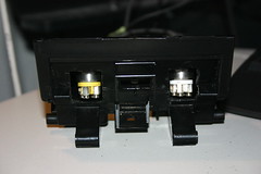
And here's the test fit of the switch assembly:
Remember: this aluminum will not be the finished state; soon when I get the mod nearly complete - I'll be powdercoating the aluminum grey to match the dash.
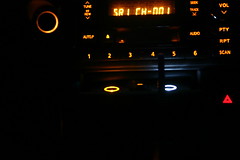
After several more hours of reassembling the ashtray and wiring in the switch assembly... here's the end result. A night shot with dash lit up and ash (I mean) switch tray extended:
(click to see full size)
Hint: The switches are visible just to the Left of the Red hazard switch.
I know... I know... you wanna see a closeup; here ya go:
(click to see full size)
The Amber LED on the rocker; only dimly lights when there is power being supplied to the PSU.
The Amber and white switch LEDs are being driving by a custom circuit I added inside the PSU body. The switch rings light based upon the state of the PSU LED. Flashing as appropriate to give me the same indication as what is going on inside the PSU. More details on the custom circuit later when I have all the kinks worked out.
Soon (maybe tomorrow); I'll post the schematics for the switch assembly.
It's been almost two weeks since I got the mini installed in the G35... it's been rock solid - working perfectly. I've only had to kill the mini once when I couldn't get control of the system when I was trying Winamp's visulation routines. The PSU does an excellent job of putting the system into standby and waking it up.
And here's the test fit of the switch assembly:
Remember: this aluminum will not be the finished state; soon when I get the mod nearly complete - I'll be powdercoating the aluminum grey to match the dash.
After several more hours of reassembling the ashtray and wiring in the switch assembly... here's the end result. A night shot with dash lit up and ash (I mean) switch tray extended:
(click to see full size)
Hint: The switches are visible just to the Left of the Red hazard switch.
I know... I know... you wanna see a closeup; here ya go:
(click to see full size)
The Amber LED on the rocker; only dimly lights when there is power being supplied to the PSU.
The Amber and white switch LEDs are being driving by a custom circuit I added inside the PSU body. The switch rings light based upon the state of the PSU LED. Flashing as appropriate to give me the same indication as what is going on inside the PSU. More details on the custom circuit later when I have all the kinks worked out.
Soon (maybe tomorrow); I'll post the schematics for the switch assembly.
It's been almost two weeks since I got the mini installed in the G35... it's been rock solid - working perfectly. I've only had to kill the mini once when I couldn't get control of the system when I was trying Winamp's visulation routines. The PSU does an excellent job of putting the system into standby and waking it up.
Thread Starter
|
Registered User
Joined: Oct 2006
Posts: 22
Likes: 0
Now for the working part of the PSU mod and how the ashtray switches were wired:
(This Design is Copyright 2006 by John Zitterkopf. ALL RIGHTS RESERVED!
Terms of use:
Free for individuals for PERSONAL use.
Business MAY NOT build, include, or sell this product for any reason without prior WRITTEN consent from John Zitterkopf)
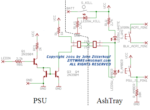
BATT = Battery Voltage From wireing harness
VCC = Battery Voltage to circuit and PSU
LEDIN is connected to active Side of the LED in the PSU... on the circuit board.
GND is obviously car ground via wireing harness.
GRN_ACPI_MINI & BLK_ACPI_MINI make up the Mac Mini's power switch. The signals were wired-or into the existing PSU harness ordered from mp3car.com. It's tied to S_WHITE, the white LED switch (for the mac mini).
PSU_J1_Pin1 is the remote power up signal to the PSU. This signal must go from GND to Battery Voltage back to GND to power up the power supply without the ignition. See the PSU manual for more detail. R_AMBER (10kohm) pulls this signal to ground when the switch button isn't depressed. The other sides of S_AMBER (the push switch with amber LED).
S_KILL is the black rocker switch with the amber LED. It removes power from the PSU and thereby the macmini if necessary. The LED for this switch is tied to ground through a 3.6K ohm resistor to keep the current at ~16V/3.6K = ~4.5mA. This small current was necessary to keep the battery drainage to a minimal value.
Q1, Q3, Q4 are 2N3904 transistors configured in a current mirror configuration. What's a current mirror you ask?
(bottom of page)
http://virtual.cvut.cz/dyn/examples/...tronic/mirror/
Basically the reference current through the emitter Q1 is "mirrored" onto the collector of Q4. This was done for several reasons; one of which is to minimize the "load" to the pin of the microcontroller driving the LED on the original PSU board. RC1 and RB1 cause the "on" current to be ~7mA at Q1E which means that the current through both of our vandal LEDs is ~7mA. RB1 limits the current draw on the pin of the microcontroller based on IB = IC/beta or ~7mA/50 = 140uA ; minisule compared to the 10's of mAs being supplied to the onboard LED.
LED_SW* are wired so that most of the LED current (~7mA) flows through the amber LED. RLW is chosen big to limit the amount of current through the white LED - to minimize it's brightness. As designed the white led should draw 2mA of current while the amber draws the remaining 5mA. A highly bright White LED would easily overwhelm the stock amber colors of the G35 dash. RL drops the voltage from BATT to ~2.3V needed across the Amber LED.
Expect an update of this circuit when I get the other aspects of the PSU mod debugged and verified.
(This Design is Copyright 2006 by John Zitterkopf. ALL RIGHTS RESERVED!
Terms of use:
Free for individuals for PERSONAL use.
Business MAY NOT build, include, or sell this product for any reason without prior WRITTEN consent from John Zitterkopf)
BATT = Battery Voltage From wireing harness
VCC = Battery Voltage to circuit and PSU
LEDIN is connected to active Side of the LED in the PSU... on the circuit board.
GND is obviously car ground via wireing harness.
GRN_ACPI_MINI & BLK_ACPI_MINI make up the Mac Mini's power switch. The signals were wired-or into the existing PSU harness ordered from mp3car.com. It's tied to S_WHITE, the white LED switch (for the mac mini).
PSU_J1_Pin1 is the remote power up signal to the PSU. This signal must go from GND to Battery Voltage back to GND to power up the power supply without the ignition. See the PSU manual for more detail. R_AMBER (10kohm) pulls this signal to ground when the switch button isn't depressed. The other sides of S_AMBER (the push switch with amber LED).
S_KILL is the black rocker switch with the amber LED. It removes power from the PSU and thereby the macmini if necessary. The LED for this switch is tied to ground through a 3.6K ohm resistor to keep the current at ~16V/3.6K = ~4.5mA. This small current was necessary to keep the battery drainage to a minimal value.
Q1, Q3, Q4 are 2N3904 transistors configured in a current mirror configuration. What's a current mirror you ask?
(bottom of page)
http://virtual.cvut.cz/dyn/examples/...tronic/mirror/
Basically the reference current through the emitter Q1 is "mirrored" onto the collector of Q4. This was done for several reasons; one of which is to minimize the "load" to the pin of the microcontroller driving the LED on the original PSU board. RC1 and RB1 cause the "on" current to be ~7mA at Q1E which means that the current through both of our vandal LEDs is ~7mA. RB1 limits the current draw on the pin of the microcontroller based on IB = IC/beta or ~7mA/50 = 140uA ; minisule compared to the 10's of mAs being supplied to the onboard LED.
LED_SW* are wired so that most of the LED current (~7mA) flows through the amber LED. RLW is chosen big to limit the amount of current through the white LED - to minimize it's brightness. As designed the white led should draw 2mA of current while the amber draws the remaining 5mA. A highly bright White LED would easily overwhelm the stock amber colors of the G35 dash. RL drops the voltage from BATT to ~2.3V needed across the Amber LED.
Expect an update of this circuit when I get the other aspects of the PSU mod debugged and verified.
Thread Starter
|
Registered User
Joined: Oct 2006
Posts: 22
Likes: 0
This weekend; I spent part of Sunday hardwiring the GPS into my G35.
I was having problems "locking" to the GPS satellites using the GPS as a standalone unit in the front window while sitting infront on the compass on the G35 dash. As far as I know my front window did not have Tint installed ... as it's clear; but there have been documented cases were tint cased problems.
However, the real reason I decided to put the GPS system in the back was to fit within the theme of my mod... keeping it looking stock. Yes; I COULD have install a stock GPS antenna onto the roof of the G35 - but I couldn't find a quick and easy source for that antenna. Instead I decided to put a suctioncup mounted shelf and the antenna in the back window where it would be hidden from view of the rear-view mirror.
http://www.flickr.com/photos/52968060@N00/302469853/
Why go through the trouble of even mounting an antenna? Well; I decided I wanted to hide the bluetooth GPS receiver in the trunk of the G35. I didn't want heat or UV deteriating the plastics of the GPS receiver. That and the flashing lights of the receiver might distract --- I mean anoy-- me and other drivers. This way I can keep stuff looking cleaner.
I measured the GPS's power draw. My Holux GPSlim236 came with a 12V adapter capable of delivering 850mA - being an engineer myself; I knew there was a buffer associated with that number. So; I measured the current draw.
While charging from complete battery drain = Icharge = ~220mA
While charging and running = Icr = ~270mA
While running w/ no battery = Inb = ~50mA
When fully charged; the device runs at ~50mA
Originally I toyed with the idea of comming up with some exotic 555timer based circuit which would keep the GPS powered by it's battery... and also keep it battery charged for a while when the ignition was off. However - Armed with this knowledge; I decided that 50mA wouldn't be a huge drain on the battery... so I decided to simply hardwire the GPS psu into the battery circuit of the G35.
First, I needed to modify the PSU for hardwired operation. I desolder the positive spring and the negative clip from the circuit board and attached red for positive and green for negative. Small gauge wire here as we won't be carrying much amperage here.
http://www.flickr.com/photos/52968060@N00/302469853/
Reassemble and reuse the 12V adapter's body:
http://www.flickr.com/photos/52968060@N00/302467088/
My G35 is equipped with the BOSE audio - which means the amp is located under the rear window inside the trunk. A perfect place to tap 12V battery power from. So; I looked at the drawings for the BOSE amp's power input and found Vbattery and GND. Verified with my DVM; and soldered in the GPS' power leads:
http://www.flickr.com/photos/52968060@N00/302467092/
Double-Sticky tapped the adapter right next to the amp:
http://www.flickr.com/photos/52968060@N00/302467090/
Poked a hole into the top liner of the trunk and placed the GPS right under the trunk light were I could get easy access to the power switch and antenna port. Secured the GPS to the liner using the "hook" portion of a velcro.
http://www.flickr.com/photos/52968060@N00/302467094/Why Velcro? Well; I wanted to be able to remove the gps unit if I need to move it... or if I need to replace it. Velcro makes that easy and possible.
The self sticky back of the velcro came off during my tests today; so I hot glued the velcro to the back of the gps unit. That should work long term. :fingers crossed:
Here's a gps screenshot showing the system in action:
http://www.flickr.com/photos/52968060@N00/302515736/
I was having problems "locking" to the GPS satellites using the GPS as a standalone unit in the front window while sitting infront on the compass on the G35 dash. As far as I know my front window did not have Tint installed ... as it's clear; but there have been documented cases were tint cased problems.
However, the real reason I decided to put the GPS system in the back was to fit within the theme of my mod... keeping it looking stock. Yes; I COULD have install a stock GPS antenna onto the roof of the G35 - but I couldn't find a quick and easy source for that antenna. Instead I decided to put a suctioncup mounted shelf and the antenna in the back window where it would be hidden from view of the rear-view mirror.
http://www.flickr.com/photos/52968060@N00/302469853/
Why go through the trouble of even mounting an antenna? Well; I decided I wanted to hide the bluetooth GPS receiver in the trunk of the G35. I didn't want heat or UV deteriating the plastics of the GPS receiver. That and the flashing lights of the receiver might distract --- I mean anoy-- me and other drivers. This way I can keep stuff looking cleaner.
I measured the GPS's power draw. My Holux GPSlim236 came with a 12V adapter capable of delivering 850mA - being an engineer myself; I knew there was a buffer associated with that number. So; I measured the current draw.
While charging from complete battery drain = Icharge = ~220mA
While charging and running = Icr = ~270mA
While running w/ no battery = Inb = ~50mA
When fully charged; the device runs at ~50mA
Originally I toyed with the idea of comming up with some exotic 555timer based circuit which would keep the GPS powered by it's battery... and also keep it battery charged for a while when the ignition was off. However - Armed with this knowledge; I decided that 50mA wouldn't be a huge drain on the battery... so I decided to simply hardwire the GPS psu into the battery circuit of the G35.
First, I needed to modify the PSU for hardwired operation. I desolder the positive spring and the negative clip from the circuit board and attached red for positive and green for negative. Small gauge wire here as we won't be carrying much amperage here.
http://www.flickr.com/photos/52968060@N00/302469853/
Reassemble and reuse the 12V adapter's body:
http://www.flickr.com/photos/52968060@N00/302467088/
My G35 is equipped with the BOSE audio - which means the amp is located under the rear window inside the trunk. A perfect place to tap 12V battery power from.
So; I looked at the drawings for the BOSE amp's power input and found Vbattery and GND. Verified with my DVM; and soldered in the GPS' power leads:http://www.flickr.com/photos/52968060@N00/302467092/
Double-Sticky tapped the adapter right next to the amp:
http://www.flickr.com/photos/52968060@N00/302467090/
Poked a hole into the top liner of the trunk and placed the GPS right under the trunk light were I could get easy access to the power switch and antenna port. Secured the GPS to the liner using the "hook" portion of a velcro.
http://www.flickr.com/photos/52968060@N00/302467094/Why Velcro? Well; I wanted to be able to remove the gps unit if I need to move it... or if I need to replace it. Velcro makes that easy and possible.
The self sticky back of the velcro came off during my tests today; so I hot glued the velcro to the back of the gps unit. That should work long term. :fingers crossed:
Here's a gps screenshot showing the system in action:
http://www.flickr.com/photos/52968060@N00/302515736/
Thread Starter
|
Registered User
Joined: Oct 2006
Posts: 22
Likes: 0
While in MS for turkey-day; My brother and I decided to try our hand a powdercoating.
The victim is the LCD housing, which is currently in brushed aluminum:
Since I was visiting with family; ripping apart the dash to remove the entire LCD assembly wasn't an option. So I simple removed the front cover from the 4 screws in the back. Since the front cover had a few scratches; I sanded it by hand using some 160grit sand paper and some scotch bright. This was done to give the face a good base for the powder coating:
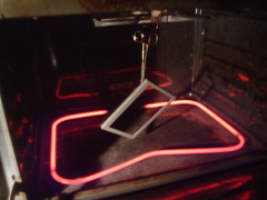
Then we powder coated it with some grey wrinkle powder and put into the junkyard oven for curing:
After 20minutes of curing; here's the result... intended to match the dash of my G35:
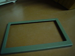
The texture doesn't exactly match the stock dash; but it is huge improvement over the brushed metal look.
And the final result; installed:
Looks much better than the brushed aluminum frame; IMHO!
I look forward to powdercoating the other peices when I disassemble the dash next time.
The victim is the LCD housing, which is currently in brushed aluminum:
Since I was visiting with family; ripping apart the dash to remove the entire LCD assembly wasn't an option. So I simple removed the front cover from the 4 screws in the back. Since the front cover had a few scratches; I sanded it by hand using some 160grit sand paper and some scotch bright. This was done to give the face a good base for the powder coating:
Then we powder coated it with some grey wrinkle powder and put into the junkyard oven for curing:
After 20minutes of curing; here's the result... intended to match the dash of my G35:
The texture doesn't exactly match the stock dash; but it is huge improvement over the brushed metal look.
And the final result; installed:
Looks much better than the brushed aluminum frame; IMHO!
I look forward to powdercoating the other peices when I disassemble the dash next time.
Thread Starter
|
Registered User
Joined: Oct 2006
Posts: 22
Likes: 0
Up until last night; I've been busy modifying CDMaster32 to allow me to convert my MP3 collection using two normalizing techniques: ReplayGain and VLevel dynamic compression in large batches. Why? The idea is that after converting all these files - I should never have to touch the volume of my car stereo between songs.
As of last night; I had sucessfully converted all of my files without crash or user prompts. The whole CDMaster32 modification was quite an endeavor. This Big Batch conversion process will be part of CDMaster32 V6.0 whenever it's released. I haven't decided if I'm going to release a "pre-review" or "macmini G35" edition of the software yet. Put your vote in now. :lol:
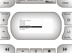
Today I turned my attention to the stock Winamp interface. It's difficult to navigate while on the road/without a non-finger pointer device. I searched all around the winamp.com/google/mp3car.com looking for a G35 Winamp interface. Any projects on Mp3car.com's forums were old, outdated, and the links were dead. Eventually I stumbled across this "modern Winamp Skin" titled: CarTouchscreenInterface by martin.deimos of the SkinConsortium.com.
His stock default interface is shown in this post:
http://forums.skinconsortium.com/vie...hp?p=4170#4170
I didn't really like any of his color choice for my project (ohnos, it's red) so a little more research and surfing of his skin files located the: gamma-presets.xml file in his xml folder of the cti.wal file. I knew this was the key to me being able to change the colors of his skin. A little more google research turned up RGB-HSL-Gamma Worker which allowed me to WYSIWYG some color choices and create some custom gamma profiles which I could insert into his file.
Here's what I came up with. I came up with two initial "daytime" color schemes:
(Remember to click pictures for original sized images)
Grey on White {daytime}
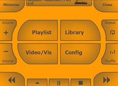
Grey on Amber {daytime alt}
and one Nite-time color theme:
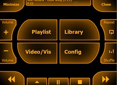
Amber on Black {night time}
I think these are a step in the right direction - but I'll have to try them after Austin's Ice storm is over.
I've included the new skin for winamp 5 on Zittware.com @
http://www.zittware.com/mod/G35_mini/CTI.wal
BTW: if you use the skin; Consider a Donation of $5 to the author's crew.
---
I played around with each of the Winamp skins today... had plenty of time while driving into work. Seems like everyone was going to work at ~10:30am today... obviously they were waiting for the thawing to start. When my 5minute commute turned into ~40minutes - I had plenty of time with the skins.
Here's my verdict:
1) The skin is very good. big buttons; readable; and useful. Right now the buttons feel well placed. About the only thing I'd change (other than previous discussion on Martin's forum) is making the song title/time area bigger fonts.
2) My Grey on Amber skin just looks to weird to me. Too much "orange" for the dash. The hue of orange doesn't even match anything on the dash. The oscope doesn't look quite right; likely because of my selections in the gamma file.
3) Grey on White. Matches the dash better. Maybe a very light "grey" background would be a better match... but the grey buttons look good. nice contrast on a overcast day. We'll see what a sunny day does to the screen.
On my way home I was able to play with the final skin in the dark.
4) Amber on black is just awesome. Not to bright... might try to do some work to match the amber better to the lit dash color.
Overall; this skin is several orders of magnitude better than the stock winamp skin for CarPuters. I'm planning on using the grey/white during day and amber on black at night until Martin comes up with the next revision of his skin.
As of last night; I had sucessfully converted all of my files without crash or user prompts. The whole CDMaster32 modification was quite an endeavor. This Big Batch conversion process will be part of CDMaster32 V6.0 whenever it's released. I haven't decided if I'm going to release a "pre-review" or "macmini G35" edition of the software yet.
Put your vote in now. :lol:Today I turned my attention to the stock Winamp interface. It's difficult to navigate while on the road/without a non-finger pointer device. I searched all around the winamp.com/google/mp3car.com looking for a G35 Winamp interface. Any projects on Mp3car.com's forums were old, outdated, and the links were dead. Eventually I stumbled across this "modern Winamp Skin" titled: CarTouchscreenInterface by martin.deimos of the SkinConsortium.com.
His stock default interface is shown in this post:
http://forums.skinconsortium.com/vie...hp?p=4170#4170
I didn't really like any of his color choice for my project (ohnos, it's red) so a little more research and surfing of his skin files located the: gamma-presets.xml file in his xml folder of the cti.wal file. I knew this was the key to me being able to change the colors of his skin. A little more google research turned up RGB-HSL-Gamma Worker which allowed me to WYSIWYG some color choices and create some custom gamma profiles which I could insert into his file.
Here's what I came up with. I came up with two initial "daytime" color schemes:
(Remember to click pictures for original sized images)
Grey on White {daytime}
Grey on Amber {daytime alt}
and one Nite-time color theme:
Amber on Black {night time}
I think these are a step in the right direction - but I'll have to try them after Austin's Ice storm is over.
I've included the new skin for winamp 5 on Zittware.com @
http://www.zittware.com/mod/G35_mini/CTI.wal
BTW: if you use the skin; Consider a Donation of $5 to the author's crew.
---
I played around with each of the Winamp skins today... had plenty of time while driving into work. Seems like everyone was going to work at ~10:30am today... obviously they were waiting for the thawing to start. When my 5minute commute turned into ~40minutes - I had plenty of time with the skins.
Here's my verdict:
1) The skin is very good. big buttons; readable; and useful. Right now the buttons feel well placed. About the only thing I'd change (other than previous discussion on Martin's forum) is making the song title/time area bigger fonts.
2) My Grey on Amber skin just looks to weird to me. Too much "orange" for the dash. The hue of orange doesn't even match anything on the dash. The oscope doesn't look quite right; likely because of my selections in the gamma file.
3) Grey on White. Matches the dash better. Maybe a very light "grey" background would be a better match... but the grey buttons look good. nice contrast on a overcast day. We'll see what a sunny day does to the screen.
On my way home I was able to play with the final skin in the dark.
4) Amber on black is just awesome. Not to bright... might try to do some work to match the amber better to the lit dash color.
Overall; this skin is several orders of magnitude better than the stock winamp skin for CarPuters. I'm planning on using the grey/white during day and amber on black at night until Martin comes up with the next revision of his skin.
Thread Starter
|
Registered User
Joined: Oct 2006
Posts: 22
Likes: 0
For the past week or so; I've been thinking about the Skin autoswitching interface. The idea is to have the mac mini "sense" when it's dark outside and switch from the Grey/White skin to the Amber on Black skin in Winamp automagically.
I think the quickest/cheapest to path is a USB Microcontroller reading a open collector comparator. The open collector of the comparator would be pulled high to the USB microcontroller's power. This controller would be tied to the circuit below which senses the "lights" signal going in the radio's wiring harness.
I've also integrated a Buck "ACCessories to 5V" converter into the same design to give me +5V to power the usb hub and other accessories which will be added to the mod later. This regulator would "enable" with the LCD screen giving me 5V power only when the ignition is turned to ACC or running.
(This Design is Copyright 2007 by John Zitterkopf. ALL RIGHTS RESERVED!
Terms of use:
Free for individuals for PERSONAL use.
Business MAY NOT build, include, or sell this product for any reason without prior WRITTEN consent from John Zitterkopf)
http://www.flickr.com/photos/52968060@N00/372988366/
I only needed one of the LM339's so I left the others with 1206 Resistor sites incase I need to add additional "data capture" capabilities to the design. when I build this circuit; I'll pull them inputs of the comparator to ground so they don't float.
Can anyone else think of something I need to add to the design before I begin laying out the PCB?

Question regarding the Bulgin switches. I purchased one for my V1 radar detector kill switch. Given that I only have 2 wires (+/-) and the switch as 4 terminals, how would you suggest I wire it to have the LED light up on the switch? Piggy back the wires so it connects a +/- to each LED terminal? Would that cause the LED on the switch to overload or will this work?
Thread Starter
|
Registered User
Joined: Oct 2006
Posts: 22
Likes: 0
Originally Posted by Espresso
Question regarding the Bulgin switches. I purchased one for my V1 radar detector kill switch. Given that I only have 2 wires (+/-) and the switch as 4 terminals, how would you suggest I wire it to have the LED light up on the switch? Piggy back the wires so it connects a +/- to each LED terminal? Would that cause the LED on the switch to overload or will this work?
I don't own any radar detectors; I find it's easier to drive the speedlimit.
Further; the information you've given is not enough to provide a solution.
On the surface; I don't beleive your going to be able to accomplish your goals with the bulgin switch by itself - or even with a small number of components.
Bulgin switches are usually momentary "on"; meaning they are always off unless the switch is depressed with a finger.
It sounds like your trying to "kill" power to your detector for some reason; I assume to turn it off. If that is the case; a momentary will not work - Unless your going to hold your finger on the switch while you drive.

The only way to accomplish this with a momentary switch is to build an electronic latching relay around it. Unless your an electronics wiz and/or have an Electrical Engineer around you - You may not have much luck.
You would certainly need a vdrop resistor to drive the bulgin LED from Vacc or Vbattery of the car.
My suggestion would be to take this discussion to a different thread and as for advice there.