
stock Head unit, aftermarket amp and speakers


Thread Starter
|
Registered User
Joined: Mar 2008
Posts: 29
Likes: 0
so here is the list of what I have:-
2 alpine type r with crossover
1 alpine type r 6*9
4 channel rockford amp
stinger wiring kit.
so everything was plug and play sort of , but I have a broblem that i'm facing right now, the stock mid panel speakers are not too deep and the after market ones are way deeper, therefore i'm keeping the stock ones. now the Q how can I run the stock amp with mid panel, and the other 4 speakers with the amp, by keeping both. and I would like to have the diagram for 2003 coupe Bose.


You probably just need speaker spacers.
www.zenclosures.com
They'll give you the clearance you need.
www.zenclosures.com
They'll give you the clearance you need.
Thread Starter
|
Registered User
Joined: Mar 2008
Posts: 29
Likes: 0
aren't they for the front speakers ?, my front speakers didn't need any spacers. they won't fit cause the speakers are too deep. do you know if they replace the mid rear speaker
Trending Topics
Thread Starter
|
Registered User
Joined: Mar 2008
Posts: 29
Likes: 0
ok guys... i'm ma3ans buddy..
he's trying to install aftermarket speakers and an amp with the stock bose headunit on a G35 coupe.
so far we have replaced the rear 6*9 speakers, the door woofers and tweeters. we left the stock speakers for the rear passengers in.
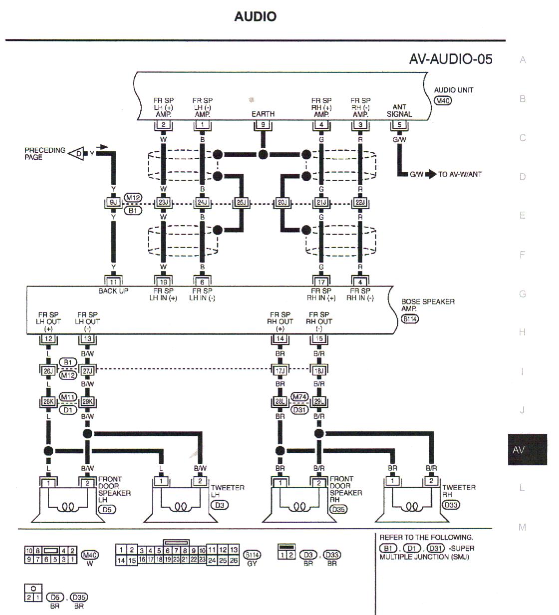
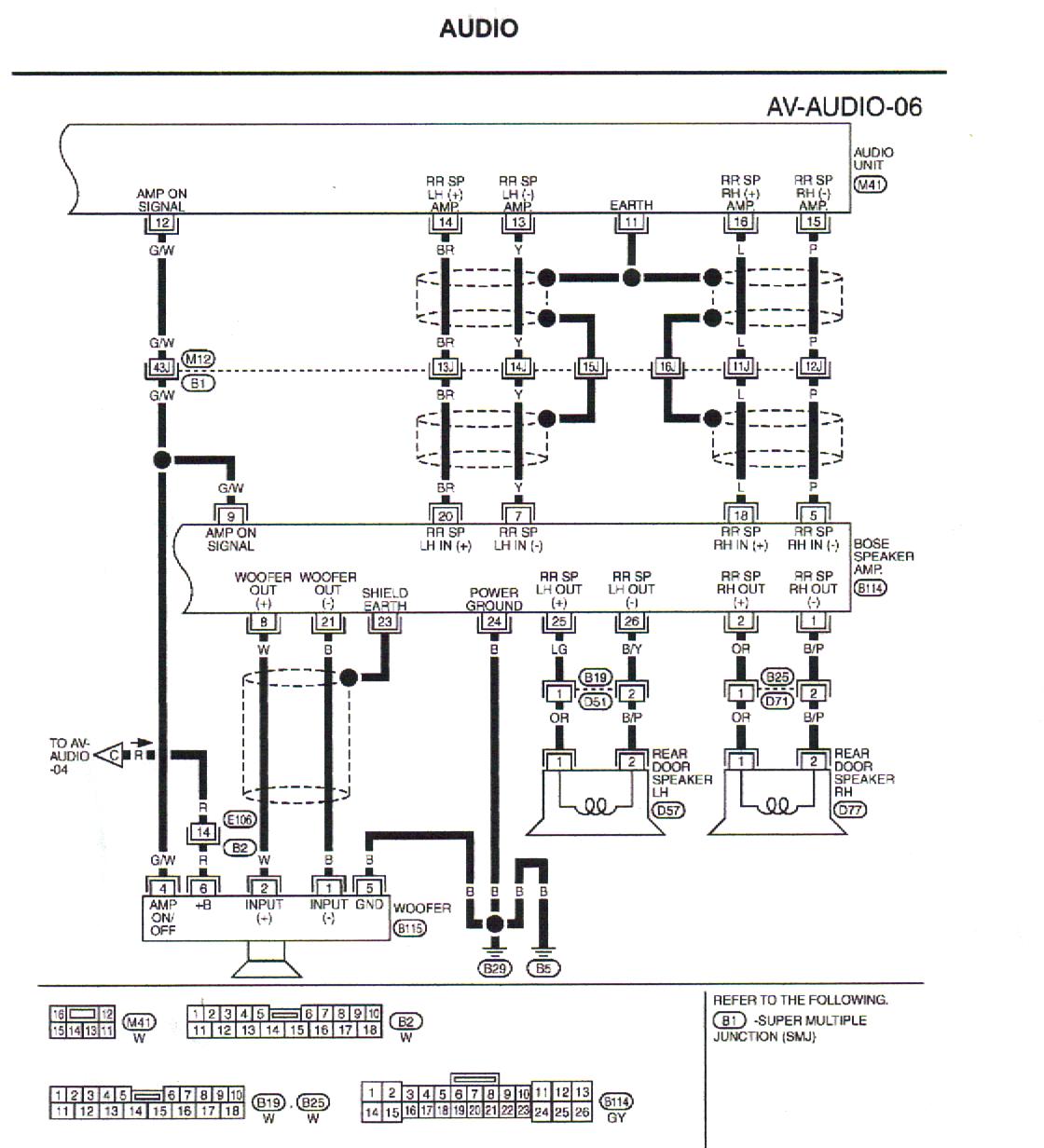
We installed the amp and got the ground, 12V and remote turnon wires installed and works like a charm. we were looking at the speaker wire pairs that come to the factory bose amp and took out 4 strands of 2 wire pairs.
1. Front Left
+
-
2. Front Right
+
-
3. Rear Left
+
-
3. Rear Right
+
-
We connected these wire pairs to the amp. now it's time to get the signal to the amp but it has RCA plugs so we got 2 x 2channel LOCs. we connected 1 and 2 (from the little illustration above) to the LOC then ran the RCAs to the amp.
Here's the problem... we get no sound.. i figured that the wires going to the amp would give a signal to the amp so i just connected that to the LOCs.
Anyone have an idea what we're doing wrong here? Is the line out converter connected to the speaker wires going into the amp? we dissconnected those to bypass the bose amp or is there a separate wire pair bringing the singal from the HU to the amp and then the amp pushes the amplified signal to the speaker wires.
he's trying to install aftermarket speakers and an amp with the stock bose headunit on a G35 coupe.
so far we have replaced the rear 6*9 speakers, the door woofers and tweeters. we left the stock speakers for the rear passengers in.
We installed the amp and got the ground, 12V and remote turnon wires installed and works like a charm. we were looking at the speaker wire pairs that come to the factory bose amp and took out 4 strands of 2 wire pairs.
1. Front Left
+
-
2. Front Right
+
-
3. Rear Left
+
-
3. Rear Right
+
-
We connected these wire pairs to the amp. now it's time to get the signal to the amp but it has RCA plugs so we got 2 x 2channel LOCs. we connected 1 and 2 (from the little illustration above) to the LOC then ran the RCAs to the amp.
Here's the problem... we get no sound.. i figured that the wires going to the amp would give a signal to the amp so i just connected that to the LOCs.
Anyone have an idea what we're doing wrong here? Is the line out converter connected to the speaker wires going into the amp? we dissconnected those to bypass the bose amp or is there a separate wire pair bringing the singal from the HU to the amp and then the amp pushes the amplified signal to the speaker wires.
Last edited by Ma3aN; Nov 18, 2010 at 12:17 AM.
Well, LOCs generally take a speaker-level input and convert it into the line output for amps that can't take speaker-level input themselves.
From what I'm reading is that you've taken a low-level, differential-balanced signal, and fed it into a converter that lowers the level of a signal, doesn't unbalance it, and are then using that to feed the amp. You don't say what kind of amp, but if it's not built to handle unbalanced signals, it'll be at best, an unclean signal for it, and using an LOC to lower it, is going to make it extremely low if it even gets through.
An RCA plug is just a plug, get a short RCA cable, cut it in half, and use that in place of the LOCs and see if you get some sound out of it.
Thread Starter
|
Registered User
Joined: Mar 2008
Posts: 29
Likes: 0
Thought some of you guys might like this
However, when looking at the line level outputs (signal from the deck) there are 4 wire pairs and then there are also 4 wire pairs going to the speakers:
As listed in the document my color for the wires don't quite match... For the line level outputs, all wires are accounted for but they are in no logical order.. white seems to be a pair with orange but really should be matched with black for + and - respectively.
Even more confusing is that for the amplifier output to the speakers there is no black/white, black/red, or black/pink. In addition, brown is listed as right front mid + but there is only one brown in the wiring bundle and i assumed that to be for line level output left rear +.
does all this make sense? anyone who's done this mod, could you shoot some pics of the install and what wires you actually used?
We didn't use LOCs afterall.

