When you click on links to various merchants on this site and make a purchase, this can result in this site earning a commission. Affiliate programs and affiliations include, but are not limited to, the eBay Partner Network.
Double Din Multimedia Install factory AC board cut down and steering wheel control
This thread is going to be a consolidation of information about installing a Android multimedia center to the G35 / G35x cars. I’m working on this in spare time as I can because I have quite a few projects going on right now.
This all started when I bought my 2004 G35x early this summer and decided to just throw a MP3 capable head unit in the car…. I soon found out that it was going to cost hundreds just to adapt the AC controls alone!! I said to myself why would they integrate the AC controls and the CD/Radio???!!! That’s just crazy. But it makes for big bucks when the CD player craps out and your AC controls stop too. hahaha that’s a good one Infiniti, the joke is on us….
Well I have been in the electronics field for over 20 years now so I thought I would take a stab at it. First thing I did was hit the junkyard for some complete control boards with CD units to start tearing apart and tracing everything.
What I installed:
I used a Android 7.1 double DIN 7” with GPS/Video/MP3/Torque OBD2 blah blah has pretty much everything you need and more. It also has a really cool steering wheel interface built in that accepts the resistive style steering wheel switches that we have in the G35. All you have to do is connect 3 wires and use the built in app to learn the buttons. I set mine up exactly as original IE: Power on/off = Power on/off and volume up/down = volume up/down etc etc…. I have even thought about adding a second set of steering wheel controls in the back for the kid.
Link to the android unit that I used in this build - $160 with wiring
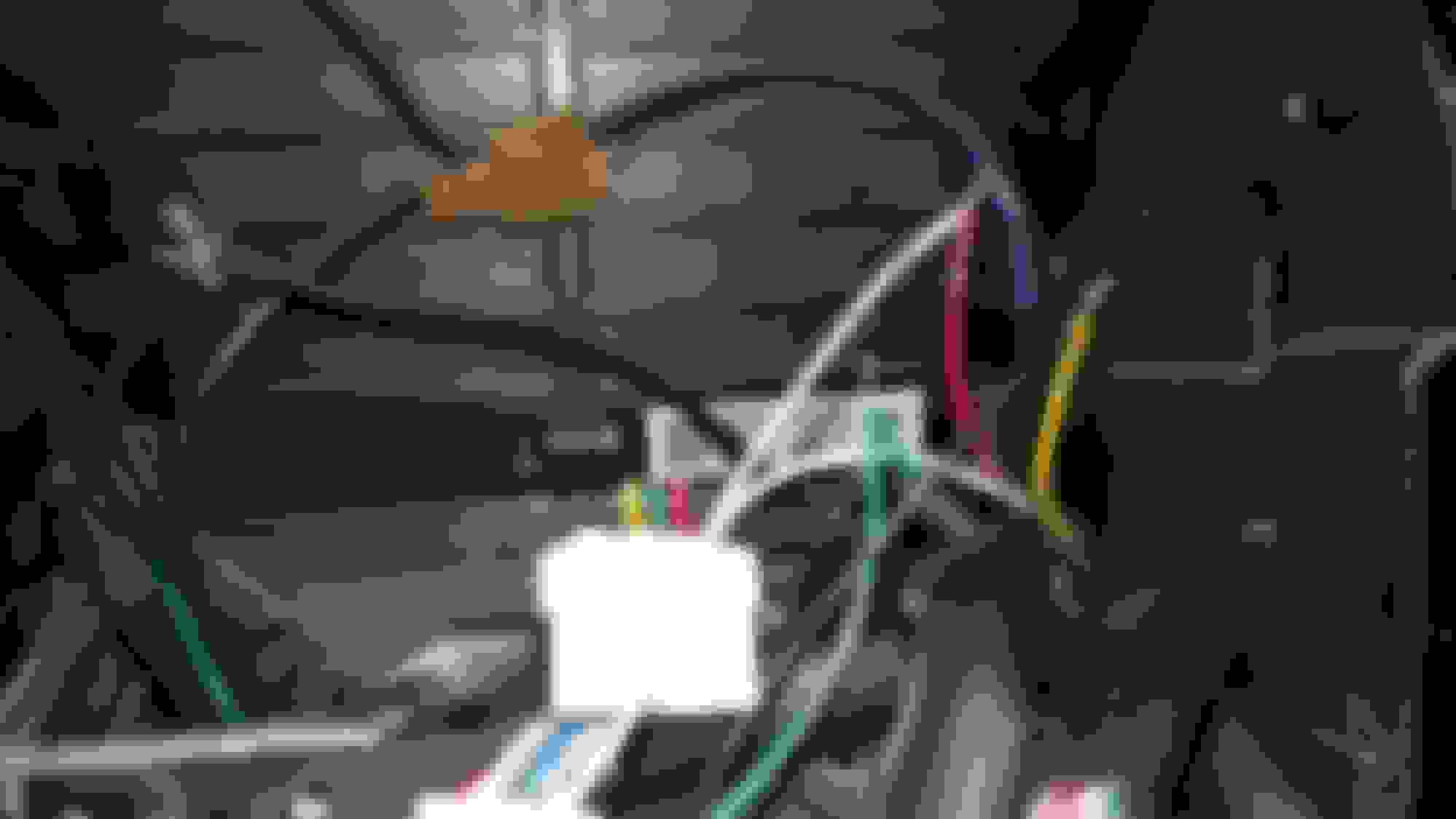
I basically wired it in straight up. You can use a line level converter to adjust / soften the volume to the amp but I really didn’t think it was necessary and works fine for me as is.
Black (Negative GND) --------------------------------------Black (from both connectors) Pin K & F Note:also connect steering wheel 16pin connector Yellow wire
Red (Positive ACC) -----------------------------------------Red + Blue (Large connector) + Blue/White (Small connector) Pin G,N,B
Brown (Back)
Pink (SW1) Use for steering wheel --------------------------------- To 16 pin connector RED wire
Grey/Black stripe (Front R-) ------------------------------Grey Black stripe = Pin O
Grey (Front R+) ----------------------------------------------Grey = Pin I
White/ Black stripe (Front L-) -----------------------------White Black stripe = Pin P
White (Front L+) ----------------------------------------------White = Pin J
Row #2 (Bottom)
Yellow (B+ Battery) -------------------------------------------Yellow = Pin M
Orange (+Ill) ---------------------------------------------------Orange = Pin H
Green/White Stripe (SW2) Use for steering wheel ------------------------ To 16 pin connector GREEN wire
Blue (Ant) Not used
Green/Black Stripe (Rear L-) -----------------------------Green Black stripe = Pin E
Green (Rear L+) ---------------------------------------------Green = Pin D
Purple (Rear R+) --------------------------------------------Purple = Pin A
Purple/Black Stripe (Rear R-) ----------------------------Purple Black stripe = Pin C
------------------------------------------------------------------------------------------------------------------
Steering wheel wiring:
G35 harness ----------------------- Android harness
Yellow (GND) ---------------------- Black (GND) ground to frame and android
Green ----------------------------- Green (SW2)
Red ------------------------------- Pink (SW1)
Adding AC control board model #'s
28041-AM660 2003 G35 Single zone climate control
28041-AM822 2003 G35 Dual zone climate control
28041-AC360 2004 G35 Single zone climate control
28041-AC370 2004 G35 Dual zone climate control
28041-AC706 2005 & 2006 Dual zone climate control
27500-AL501 JDM Dual Zone (fits 03-04 dash)
Cutting the AC control board down:
This is something I did just to say I could do it. I have over 10 hours of work just to trace the ac control board, car wiring harness, and cd deck to figure it all out. The board has to be cut extremely close to one of the IC’s so a lot of traces have to be relocated. Also the power supply is built into the CD player so I had to make another to add into the ac board. Another issue is that 2003,2004,and 2005 use different boards and have different layouts! I have finished 03 and 04 boards and am working on 05' now. I don’t know if I’ll ever find the time to do a DIY write up for something like this and if it’s really worth the time and effort. I just thought it was a cool thing to do at the time. Other options besides doing this is a used JDM AC board ($80-$150) or an aftermarket radio kit ($200+)
Cutting the radio bezel and mounting the deck:
This was very simple. Put blue painters masking tape over the display so I wouldn’t scratch it. Then I took the steel cage and inserted the Android radio. Then I set the rado bezel over the radio steel cage to see how much needed to be cut out. Used a dremel with cutoff wheel and a flat steel file to cut out. I made two different bezels to see what I liked better. One cut exactly where the face fit into it perfectly. And one rough cut and used the included din finisher the pops over the front to cover up any gaps. After I decided how I wanted it I used a micrometer and a sharpie to mark the steel cage for the side screws to make it permanent.
Notes on 2005 install:
Front rosewood radio bezel is wrapped aluminum over plastic. It is extremely hard to cut with a dremel, I used a 4 1/2" angle grinder. I had to be careful when cutting it so the metal didn't get too hot and destroy the rosewood overlay.
Steering wheel wiring - I had some trouble with the steering wheel programing until I ran a direct ground to frame. The antenna ground and radio ground was a floating ground and made the steering wheel functions act weird.
work in prog�ress
an unfinished project that is still being added to or developed.
Last edited by scumbagsleeper; Jan 18, 2019 at 09:44 AM.
These are old videos when I first started working on the boards. They are not cut down completely and are far from finished height. I'll try to get some newer updated videos soon.
2003 rev1 board cut and bypassed - Youtube link
Great work! About how many wires are needed to be soldered onto the board to bypass the CD player? The only other successful way around a JDM or Metra control board was somebody who literally soldered every single wire from one half of the board to the other (which they tucked in behind the new radio). It was a horrible mess, but I suppose it worked.
@ Wrathernaut : I saw that install and it made me cringe thinking about all of those wires with heat/cold and vibration. About how many wires, I really haven't counted (I guarantee less than half of that other guy hahaha) plus it's a little more than just the wires since I have two other PCB's wired to the back to make it functional. It's still a work in progress and I'm still trying to simplify it and make some deletions. It's kind of hard to fit in working on 2003, 2004, 2005 PCB layouts since they are all slightly different and soaking up more time...
Edit: I'm pretty sure 2006 will have the same PCB as 2005 but if anyone has a pic of a 2006 climate control I would love to see it.
Thanks, I just found that out looking up the part #'s the other day... 28041-AC706
I did finally get the control board finished. Man that was a lot of work... I still want to clean up some things and make a few deletions but at least it's fully functional! Tracing everything from both sides of the PCB took most of the time since a bunch of the lines hop in and out so many times.
Sorry for bringing this back from the dead, but currently the JDM boards don't seem to be available anywhere, and even then I have been told from the sellers that the dual zone function does not work on US cars. Don't know what to think, but it makes this level of work seem worthwhile given there is no other great option.
Sorry for bringing this back from the dead, but currently the JDM boards don't seem to be available anywhere, and even then I have been told from the sellers that the dual zone function does not work on US cars. Don't know what to think, but it makes this level of work seem worthwhile given there is no other great option.
They pop up on eBay occasionally. There is also a Japanese parts site that has new ones listed for about $300 before shipping (assuming it is actually in stock). I still need one as well.
Thanks, I just found that out looking up the part #'s the other day... 28041-AC706
I did finally get the control board finished. Man that was a lot of work... I still want to clean up some things and make a few deletions but at least it's fully functional! Tracing everything from both sides of the PCB took most of the time since a bunch of the lines hop in and out so many times.
Sorry for reviveing such a old thread but I had been thinking about starting a project with my g for fun and was looking to see if you have any info on the traces you did. I want to do a all touch screen for radio and heater controls but want to keep the heater controls for OEM harness purposes but clearly need to trim down the board as you did. I don't need to fit a din so can I just cut down the bottom to stuff it in the hole that the radio left. Or will that still cause problems with the board?
Cutting any of the board will require reconnecting traces. Also you will have to make a power supply to drive the board since the CD unit has the board power supply in it. I was going to make a schematic but lost interest after spending countless hours on the few I converted. There are multiple revisions of boards and the traces are different on each. After doing them I understand why i'm the only one crazy enough to do it.