
LED under glove box/steering wheel help


Originally Posted by dcityjatt
i beeen meaning to do thiss!!!
i even bought the lights from pep boys (have had em for more than 2 months)
ne way possible if you can provide a link to this product on pepboys website?? just want to make sure i have the correct one...i think it has like 15 led's spread apart by maybe an 1 inch each?
oh i cant wait now!!
i even bought the lights from pep boys (have had em for more than 2 months)
ne way possible if you can provide a link to this product on pepboys website?? just want to make sure i have the correct one...i think it has like 15 led's spread apart by maybe an 1 inch each?
oh i cant wait now!!
Originally Posted by Deftronix
You will definitely want to tap into the map light circuit.
I actually did something similar with 4 12" white ccfl tubes.
You can get to these wires right at the BCM (in front of driver side door)
Heres a picture with the info u need (this is the connector furthest right):
Pin 1: Red/Black (+12v)
Pin 8: Purple/Red (-)

I actually did something similar with 4 12" white ccfl tubes.
You can get to these wires right at the BCM (in front of driver side door)
Heres a picture with the info u need (this is the connector furthest right):
Pin 1: Red/Black (+12v)
Pin 8: Purple/Red (-)
2) where can i find those ccfl tubes/will they get hot under rear passengers legs?
Originally Posted by dream_G35
1)Im a newb at electric work, wut do u mean by tapping in(splicing wires)? picture?
2) where can i find those ccfl tubes/will they get hot under rear passengers legs?
2) where can i find those ccfl tubes/will they get hot under rear passengers legs?

Originally Posted by Steel Blue
Is the above pic in the cabin or in the engine compartment?

the above picture, is it like a wire harness that is plugged in there? can i pull it out? or do i have to pull out each (#1, #8) of them individually?
please provide a detailed diy, if possible? would really appreciate it!!
please provide a detailed diy, if possible? would really appreciate it!!

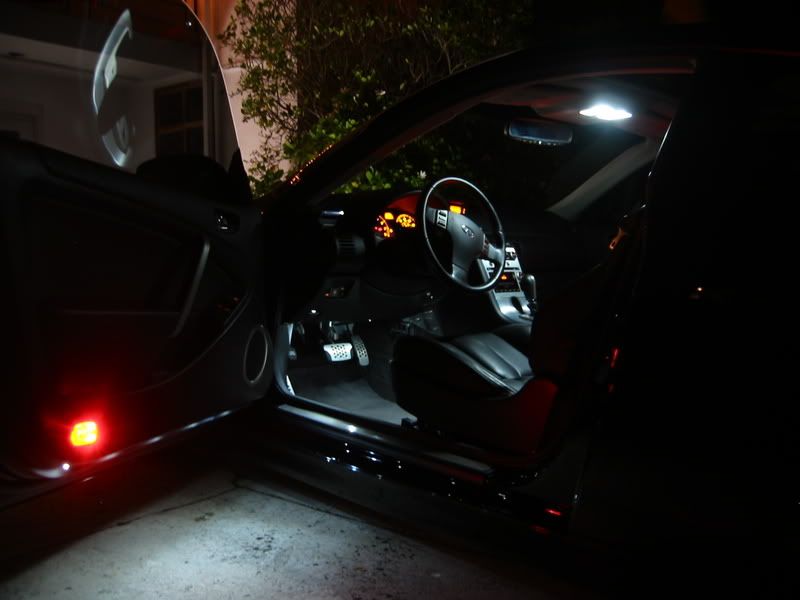
For those of you who wanted more details:
BCM Harness furthest right (near driver side foot plate. See picures below)
Use these pinouts to connect inverters/leds
Driver side:
Drill a hole a couple inches in front of the ridge in the back of the trim piece.
Now you can run a zip tie around the ccfl, through the hole and attach it.
The inverter you see in this picture was pushed in after install was completed

Passenger side:
Take out the lowerdash piece to allow enough access for installation. Use zip ties to secure.

Picure with oem trim piece reinstalled:

Rear:
Use an exacto knife or anything sharp to put 4 holes for each tube in the carpet. Thread zip ties through these holes and attach ccfl's.

I put the inverter for these tubes in the first aid compartment. (yes the first aid kit still fits)

Hope this helps! Have fun!
BCM Harness furthest right (near driver side foot plate. See picures below)
Use these pinouts to connect inverters/leds
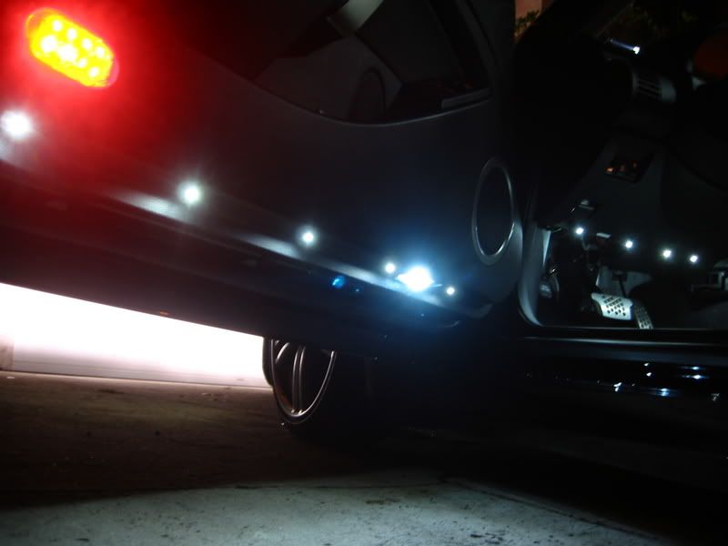
Driver side:
Drill a hole a couple inches in front of the ridge in the back of the trim piece.
Now you can run a zip tie around the ccfl, through the hole and attach it.
The inverter you see in this picture was pushed in after install was completed
Passenger side:
Take out the lowerdash piece to allow enough access for installation. Use zip ties to secure.
Picure with oem trim piece reinstalled:
Rear:
Use an exacto knife or anything sharp to put 4 holes for each tube in the carpet. Thread zip ties through these holes and attach ccfl's.
I put the inverter for these tubes in the first aid compartment. (yes the first aid kit still fits)
Hope this helps! Have fun!


Originally Posted by DHCrocks
That came out great. looks good. did you do the trunk too?

Originally Posted by Deftronix
For those of you who wanted more details:
BCM Harness furthest right (near driver side foot plate. See picures below)
Use these pinouts to connect inverters/leds
Driver side:
Drill a hole a couple inches in front of the ridge in the back of the trim piece.
Now you can run a zip tie around the ccfl, through the hole and attach it.
The inverter you see in this picture was pushed in after install was completed
Passenger side:
Take out the lowerdash piece to allow enough access for installation. Use zip ties to secure.
Picure with oem trim piece reinstalled:
Rear:
Use an exacto knife or anything sharp to put 4 holes for each tube in the carpet. Thread zip ties through these holes and attach ccfl's.
I put the inverter for these tubes in the first aid compartment. (yes the first aid kit still fits)
Hope this helps! Have fun!