
DIY: KP Technologies Auto Lock/Unlock Module

Joined: Aug 2007
Posts: 1,434
Likes: 4
From: Yorba Linda (Orange County)
DIY: KP Technologies Auto Lock/Unlock Module
OK, first off... thank you Kevin (KP Tech) for your GREAT customer service and product, 2GorNot2G for helping a lot with all my installs, and PeterUbers for his write up!
View in it's entirety for installing. I have a 07 G35s Sedan 6MT. This is for the timing mode. Also, I did NOT buy the extra relay to unlock the rear doors. This write up is to lock all doors when you start the car and unlock the front doors when car turns off.
Module:
Green Wire ==> Purple Relay Wire and Green Relay Wire.
Blue Wire ===> Blue Relay Wire.
Orange Wire => Run from door switch to orange wire OR BCM (Grey Wire) Pin 150 to Orange wire on the module.
Black Wire ==> Ground to car bolt by passenger door.
Yellow Wire => Ignition 12V (Red Wire) Pin 82 (this wire is VERY thin, be careful as it separates easily!)
Red Wire (Long) => Constant 12V to thick white wire at BCM Pin 1
Red Wire (Short) => DO NOT USE for timing mode.
Relay:
Twisted Purple/Black Wire => CUT BCM Pin 8 (Pink Wire) *Locks all doors. Connect Black wire to end going into terminal and purple wire into the other end that was cut.
Twisted Green/Black Wire => CUT BCM Pin 5 (Green Wire) *Unlock Passenger Door. Connect Black wire to end going into terminal and green wire into the other end that was cut.
Twisted Blue/Black Wire => CUT BCM Pin 9 (Purple Wire) *Unlock Drivers Door. Connect Black wire to end going into terminal and blue wire into the other end that was cut.
Purple & Green Wire => to Green Module Wire
Blue Wire ========> Blue Module Wire
Red Wire ========> Constant 12V BCM Pin 1 (White Wire)
Black Wire =======> Ground to car bolt on passenger side.
Please use .PDF I made with pictures for more clarification and location of wires and plug. The BCM is located on the passenger side under the glove box (same location of the fuse box, but on the passenger side). Panels just pop off.
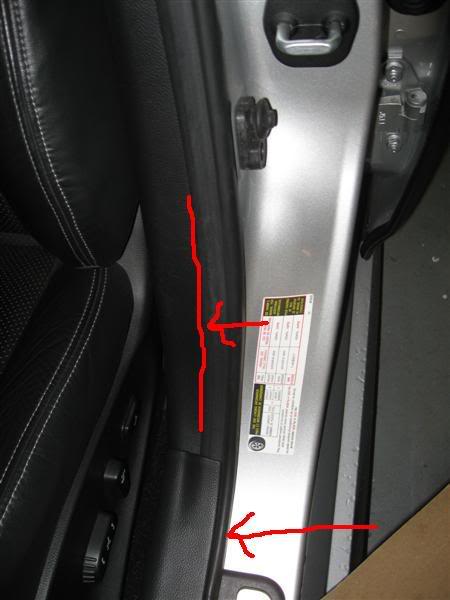
Pop the bottom panel off and separate column piece a little to get access to the drivers side switch
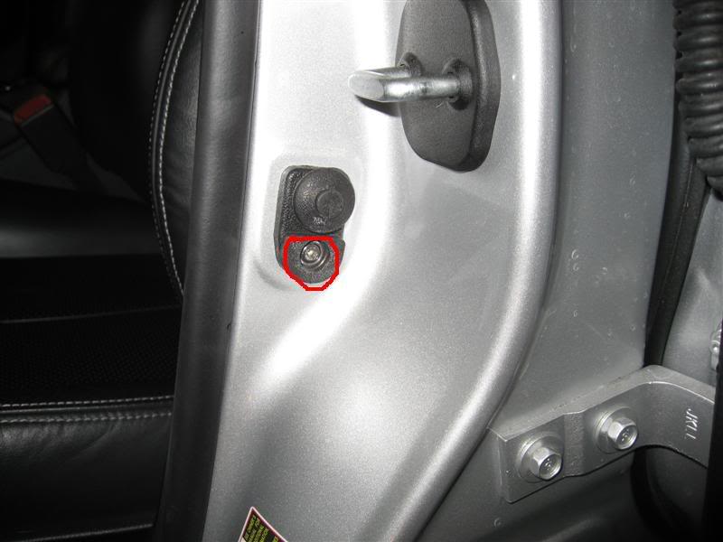
Unscrew screw and you will find Drivers Door Switch (Grey Wire) Run wire to Orange Wire Module. OR, easier way... BCM (Grey Wire) Pin 150 to Orange wire on the module
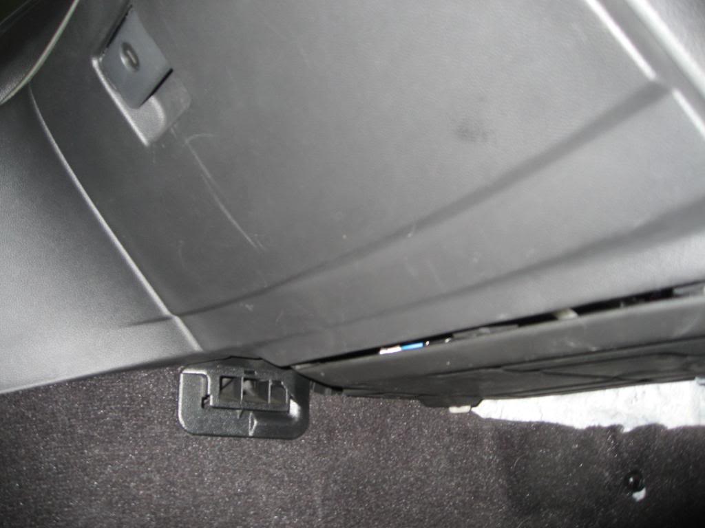
Pop this panel off
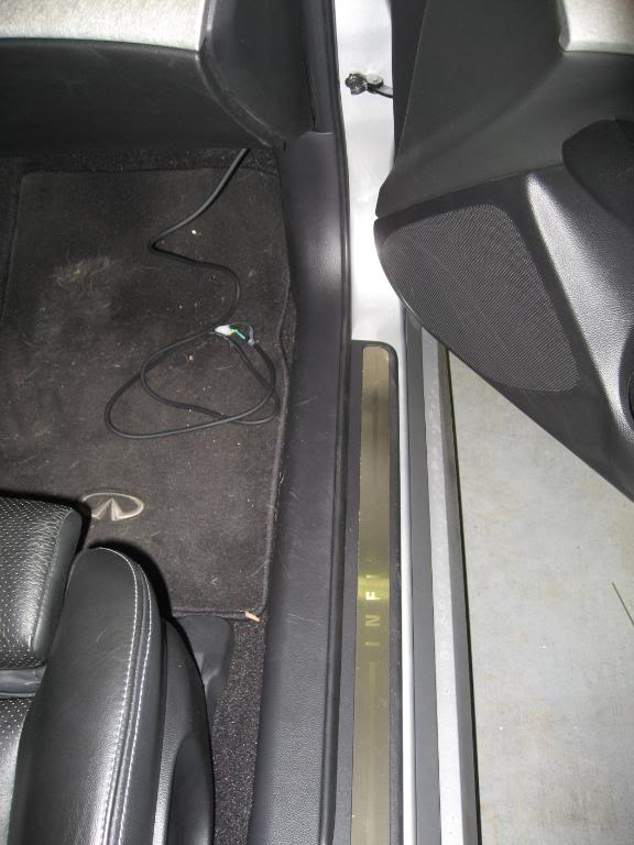
Then pop this off, there is a plastic nut to unscrew to remove panel. This will review the BCM
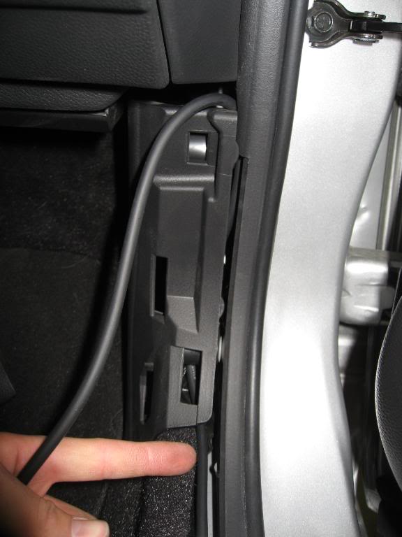
Pop this off, 3 clips in the front that pop off
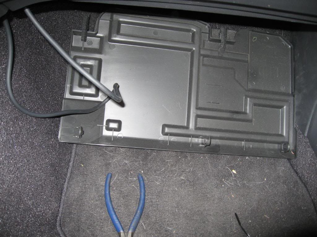
Picture of BCM
BCM and terminals you will be using
Where you will ground wire from the module and relay

Ignition 12V (Red Wire) Pin 82 (this wire is VERY thin, be careful as it separates easily!) Connect Yellow Wire to this.

Picture of terminal for lock and unlock wires and contact 12V

Another picture of the above

Terminal where you will wire all the lock and unlock wire (the twisted wires from the relay)
Which wires are what on the above picture
[B]
Tuck everything in so just the DL20 (Module) is hanging out and then tuck in by the glove compartment
View in it's entirety for installing. I have a 07 G35s Sedan 6MT. This is for the timing mode. Also, I did NOT buy the extra relay to unlock the rear doors. This write up is to lock all doors when you start the car and unlock the front doors when car turns off.
Module:
Green Wire ==> Purple Relay Wire and Green Relay Wire.
Blue Wire ===> Blue Relay Wire.
Orange Wire => Run from door switch to orange wire OR BCM (Grey Wire) Pin 150 to Orange wire on the module.
Black Wire ==> Ground to car bolt by passenger door.
Yellow Wire => Ignition 12V (Red Wire) Pin 82 (this wire is VERY thin, be careful as it separates easily!)
Red Wire (Long) => Constant 12V to thick white wire at BCM Pin 1
Red Wire (Short) => DO NOT USE for timing mode.
Relay:
Twisted Purple/Black Wire => CUT BCM Pin 8 (Pink Wire) *Locks all doors. Connect Black wire to end going into terminal and purple wire into the other end that was cut.
Twisted Green/Black Wire => CUT BCM Pin 5 (Green Wire) *Unlock Passenger Door. Connect Black wire to end going into terminal and green wire into the other end that was cut.
Twisted Blue/Black Wire => CUT BCM Pin 9 (Purple Wire) *Unlock Drivers Door. Connect Black wire to end going into terminal and blue wire into the other end that was cut.
Purple & Green Wire => to Green Module Wire
Blue Wire ========> Blue Module Wire
Red Wire ========> Constant 12V BCM Pin 1 (White Wire)
Black Wire =======> Ground to car bolt on passenger side.
Please use .PDF I made with pictures for more clarification and location of wires and plug. The BCM is located on the passenger side under the glove box (same location of the fuse box, but on the passenger side). Panels just pop off.
Pop the bottom panel off and separate column piece a little to get access to the drivers side switch
Unscrew screw and you will find Drivers Door Switch (Grey Wire) Run wire to Orange Wire Module. OR, easier way... BCM (Grey Wire) Pin 150 to Orange wire on the module
Pop this panel off
Then pop this off, there is a plastic nut to unscrew to remove panel. This will review the BCM
Pop this off, 3 clips in the front that pop off
Picture of BCM
BCM and terminals you will be using
Where you will ground wire from the module and relay
Ignition 12V (Red Wire) Pin 82 (this wire is VERY thin, be careful as it separates easily!) Connect Yellow Wire to this.
Picture of terminal for lock and unlock wires and contact 12V
Another picture of the above
Terminal where you will wire all the lock and unlock wire (the twisted wires from the relay)
Which wires are what on the above picture
[B]
Tuck everything in so just the DL20 (Module) is hanging out and then tuck in by the glove compartment
Last edited by KulG35; Feb 9, 2009 at 01:11 PM.

Excellent writeup and congrats!
How come you didn't use the pin wire at the BCM -- you ran the orange doorpin wire all the way to the driver's side...? I believe it is in the green harness of the BCM (bottom left as you look directly at it .. the pin# is in my thread and the exact location is found on the idata *pdf)
How come you didn't use the pin wire at the BCM -- you ran the orange doorpin wire all the way to the driver's side...? I believe it is in the green harness of the BCM (bottom left as you look directly at it .. the pin# is in my thread and the exact location is found on the idata *pdf)
Last edited by PeterUbers; Feb 7, 2009 at 02:31 PM.
I also thought about intalling a switch in-line with the 12 volt(+) wire to the relay module and running this switch up to the center armrest area so that I could, with a flip of a switch (or push of a push-button switch) disable the autolock/unlock....
Joined: Aug 2007
Posts: 1,434
Likes: 4
From: Yorba Linda (Orange County)
I thought it had to be there in the actual door pillar. O'well... it's working :-) just need to rescan for PDF or find a way to post a 10MB pdf
You have it in your first post:
Orange Wire (door pin) => Run wire from BCM (Grey Wire) Pin 150 to Orange wire on the module.
Oh, what amperage fuse did you put inline for the relay pack? Only the KP20 module comes with a 3 amp fuse.
Orange Wire (door pin) => Run wire from BCM (Grey Wire) Pin 150 to Orange wire on the module.
Oh, what amperage fuse did you put inline for the relay pack? Only the KP20 module comes with a 3 amp fuse.
Joined: Aug 2007
Posts: 1,434
Likes: 4
From: Yorba Linda (Orange County)
Used the same 3 amp fuse. I ran the wire from the door. Though I should have use pin 150 as you did.
Trending Topics
You used a 3amp fuse for the relay pack? the relay pack will blow with anything less than a 10 amp fuse, I had to put in another circuit breaker with a 10amp fuse (had one laying around from another project)... interesting your KP20 AND the relay pack are all getting current through the same 3 amp fuse ... or did you connect the 12 volt+ power supply wire of the relay pack directly to the fat white 12 volt wire at the bcm?
Joined: Aug 2007
Posts: 1,434
Likes: 4
From: Yorba Linda (Orange County)
You used a 3amp fuse for the relay pack? the relay pack will blow with anything less than a 10 amp fuse, I had to put in another circuit breaker with a 10amp fuse (had one laying around from another project)... interesting your KP20 AND the relay pack are all getting current through the same 3 amp fuse ... or did you connect the 12 volt+ power supply wire of the relay pack directly to the fat white 12 volt wire at the bcm?
uh .. dude, you should throw an in-line fuse on that second red wire (the one that powers the relay pack) .. you'll need a 10 amp fuse and its respect circuit breaker... don't wanna blow yer bcm:
............................................./==============(10 amp inline fuse)=========KP relay pack
white wire================<
.............................................\==== ============(3 amp fuse .. comes with)======KP20 module
............................................./==============(10 amp inline fuse)=========KP relay pack
white wire================<
.............................................\==== ============(3 amp fuse .. comes with)======KP20 module
Registered User
Joined: Nov 2008
Posts: 2,588
Likes: 24
From: SoCal
Nice write up, Travis. Glad everything is working now.
I was the one the connected the door pin ground wire and ran it to the BCM... Wish I had known there was a connection at the BCM for it already... would have saved us about 15 or 20 minutes. LOL... Oh well, it works.
The white power wire is already fused at the fuse box, but it probably wouldn't be a bad idea to add a second in-line fuse for the relay pack. I was surpirsed they didn't include in-line fuse already. Travis, we can add a fuse to this if you want when you come over to do the revese mirror tilt module.
Joined: Aug 2007
Posts: 1,434
Likes: 4
From: Yorba Linda (Orange County)
Awesome, let's do it
Nice write up, Travis. Glad everything is working now.
I was the one the connected the door pin ground wire and ran it to the BCM... Wish I had known there was a connection at the BCM for it already... would have saved us about 15 or 20 minutes. LOL... Oh well, it works.
The white power wire is already fused at the fuse box, but it probably wouldn't be a bad idea to add a second in-line fuse for the relay pack. I was surpirsed they didn't include in-line fuse already. Travis, we can add a fuse to this if you want when you come over to do the revese mirror tilt module.
I was the one the connected the door pin ground wire and ran it to the BCM... Wish I had known there was a connection at the BCM for it already... would have saved us about 15 or 20 minutes. LOL... Oh well, it works.
The white power wire is already fused at the fuse box, but it probably wouldn't be a bad idea to add a second in-line fuse for the relay pack. I was surpirsed they didn't include in-line fuse already. Travis, we can add a fuse to this if you want when you come over to do the revese mirror tilt module.

Thread
Thread Starter
Forum
Replies
Last Post
Learned Hand
G35 Sedan V35 2003-06
1
Oct 1, 2015 09:02 AM