
Please Help with some Audio Questions
#1
 05-13-2013, 04:22 PM


Please Help with some Audio Questions
Hey all,
The other day I heard one of my speakers cracking and thought its finally about time to upgrade the audio in my car. I have already upgraded the headunit but everything else is stock and I also have the bose package (regrettably :/ ) .
I would like to do audio upgrades in stages and thought some of you might know a little bit more about the specifics for the Bose system that I do.
Current Setup
Car: 2005 Infiniti G35
Type: Coupe
Factory Bose Setup except Head unit (which is PIONEER AVIC-Z110BT)
Stage 1.
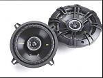
Replace 2 Front Speakers and 2 Rear Side Speakers with Kicker 40CS54 (Already Purchased).
http://www.crutchfield.com/p_2064CS5...54.html?tp=105
Stage 2.
Replace Factory Bose Amp with 5 or 6 Channel AMP.
Remove Remove the Rear Deck Lid Speakers
Stage 3.
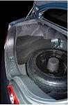
Install a JL Audio Stealthbox for the Coupe and connect to the amp purchased for stage 2.
http://www.crutchfield.com/S-wVWM56m...tealthbox.html
Questions I have
1. I spoke with an adviser at Crutchfield and they said all the speakers are 2Ohm is that true?
2. The adviser also said that replacing the 2Ohm speakers with 4 Ohm speakers would mean that it may not sound decent. Is there any truth to that?
3. Is it possible to use the factory wiring for the new speakers but bypassing the Bose amp completely and powering the speakers from the Head Unit.
I saw mention of this from Wrathernaut on this thread https://g35driver.com/forums/audio-v...e-amp-not.html but I am unsure if this has been done somewhere as I cant find any photos.
4. Are there any replacement tweeters that can be mounted using the same stock hardware (so that I don't have to fabricate a mount).
Thanks for your help guys.
The other day I heard one of my speakers cracking and thought its finally about time to upgrade the audio in my car. I have already upgraded the headunit but everything else is stock and I also have the bose package (regrettably :/ ) .
I would like to do audio upgrades in stages and thought some of you might know a little bit more about the specifics for the Bose system that I do.
Current Setup
Car: 2005 Infiniti G35
Type: Coupe
Factory Bose Setup except Head unit (which is PIONEER AVIC-Z110BT)
Stage 1.
Replace 2 Front Speakers and 2 Rear Side Speakers with Kicker 40CS54 (Already Purchased).
http://www.crutchfield.com/p_2064CS5...54.html?tp=105

Stage 2.
Replace Factory Bose Amp with 5 or 6 Channel AMP.
Remove Remove the Rear Deck Lid Speakers
Stage 3.
Install a JL Audio Stealthbox for the Coupe and connect to the amp purchased for stage 2.
http://www.crutchfield.com/S-wVWM56m...tealthbox.html

Questions I have
1. I spoke with an adviser at Crutchfield and they said all the speakers are 2Ohm is that true?
2. The adviser also said that replacing the 2Ohm speakers with 4 Ohm speakers would mean that it may not sound decent. Is there any truth to that?
3. Is it possible to use the factory wiring for the new speakers but bypassing the Bose amp completely and powering the speakers from the Head Unit.
I saw mention of this from Wrathernaut on this thread https://g35driver.com/forums/audio-v...e-amp-not.html but I am unsure if this has been done somewhere as I cant find any photos.
4. Are there any replacement tweeters that can be mounted using the same stock hardware (so that I don't have to fabricate a mount).
Thanks for your help guys.
Last edited by DBayPlaya2k3; 05-13-2013 at 04:28 PM.
#2
05-13-2013, 09:21 PM


Hey all,
The other day I heard one of my speakers cracking and thought its finally about time to upgrade the audio in my car. I have already upgraded the headunit but everything else is stock and I also have the bose package (regrettably :/ ) .
I would like to do audio upgrades in stages and thought some of you might know a little bit more about the specifics for the Bose system that I do.
Current Setup
Car: 2005 Infiniti G35
Type: Coupe
Factory Bose Setup except Head unit (which is PIONEER AVIC-Z110BT)
Stage 1.
Replace 2 Front Speakers and 2 Rear Side Speakers with Kicker 40CS54 (Already Purchased).
http://www.crutchfield.com/p_2064CS5...54.html?tp=105
Attachment 159106
Stage 2.
Replace Factory Bose Amp with 5 or 6 Channel AMP.
Remove Remove the Rear Deck Lid Speakers
Stage 3.
Install a JL Audio Stealthbox for the Coupe and connect to the amp purchased for stage 2.
http://www.crutchfield.com/S-wVWM56m...tealthbox.html
Attachment 159107
Questions I have
1. I spoke with an adviser at Crutchfield and they said all the speakers are 2Ohm is that true?
2. The adviser also said that replacing the 2Ohm speakers with 4 Ohm speakers would mean that it may not sound decent. Is there any truth to that?
3. Is it possible to use the factory wiring for the new speakers but bypassing the Bose amp completely and powering the speakers from the Head Unit.
I saw mention of this from Wrathernaut on this thread https://g35driver.com/forums/audio-v...e-amp-not.html but I am unsure if this has been done somewhere as I cant find any photos.
4. Are there any replacement tweeters that can be mounted using the same stock hardware (so that I don't have to fabricate a mount).
Thanks for your help guys.
2. Few amps that can handle 2-ohm have any problem running 4-ohm. It shouldn't be any problem. The reverse is not true, many 4-ohm amps can't handle a 2-ohm load.
3. Yes, I'm using the factory wiring from trunk to doors with mine, 150w RMS (JL 300w4v2 bridged to 2 channels) per speaker. I'm hoping somebody's got a good photo to share of the bypass at the bose amp, since you've already linked my description of the procedure.
4. There's a lot of room behind the panels, I've got the tweeters that come with the Boston Acoustics Pro60se in the factory location, completely invisible:

Sorry, I didn't take any photos of the mounted tweeter. I just bent up the stock bracket a bit to hold the larger tweeter, using high-temp hot-melt glue to hold it in. Vibration is minimal and the bracket does most the work holding it, so I'm not concerned that the mount is insecure.
#3
05-13-2013, 10:21 PM

Registered User
#4
05-13-2013, 10:25 PM
Registered User
#5
05-14-2013, 11:26 AM
Wrathernaut
Thanks for the help with the questions man it defiantly helped me out.
Hey when you did your bypass did you just soider the inputs directly to the outputs or did you use some method of a connector (maybe female and male spade terminals).
I was thinking of ways I could do it and thought maybe if i use spade terminals I can connect both sides and then keep the plug end that had been cut in case I ever needed to turn the car back to stock (in case I wired something incorrectly or something like that).
If you are using the Boston Acoustics tweeters are you using a component speaker system or just individual separate tweets from your speakers. I am worried that If I dont have a component set I will be sending full signal to the tweeters instead of just highs. Of course I am not sure how the stock bose system compensated for this.
#6
05-14-2013, 11:28 AM
SergeantRed
A DIY would be awesome I will defiantly be sending you a PM after posting this message so check your inbox. Lol ill take all the input I can get.
I too have been working on a wiring schematic with some help from the cruchfield post.
I plan on posting it soon so you guys can take a look at it and tell me what you think.
#7
05-14-2013, 11:34 AM
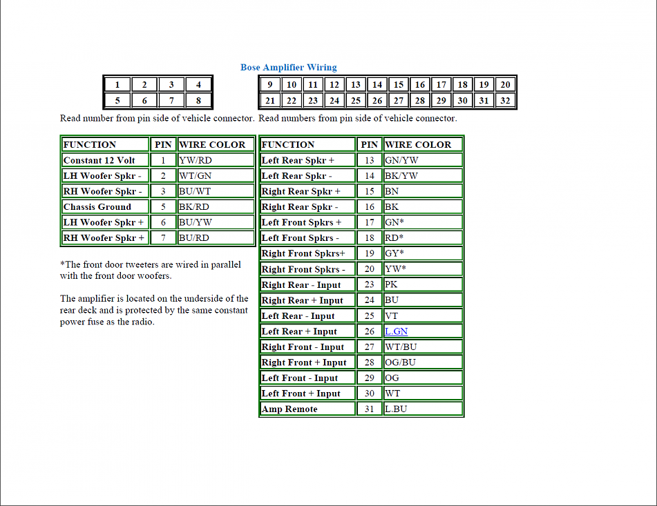
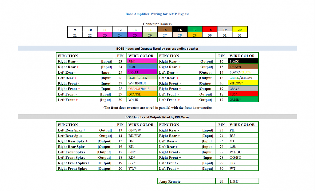
Hey guys yesterday I spoke with one of the guys at crutchfield about the bypass while I was waiting for comments and he gave me a file that shows exactly what I needed.
ORIGNAL:
Bose Amplifier Wiring ORIGNAL.pdf
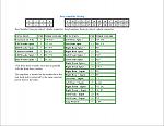
MODFIED:
Bose Amplifier Wiring for AMP Bypass FINAL.pdf
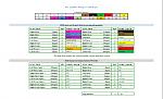
I then modified it a bit and thought it might be very helpful for anyone else trying to do a bypass.
SergeantRed This might be helpful for your DIY Guide if you have not already created your own as well.
I have not verfied the wire colors yet (as Im currently at work) but I plan to once I get home.
I thought maybe you guys could take a look and tell me what you think.
ORIGNAL:
Bose Amplifier Wiring ORIGNAL.pdf
MODFIED:
Bose Amplifier Wiring for AMP Bypass FINAL.pdf
I then modified it a bit and thought it might be very helpful for anyone else trying to do a bypass.
SergeantRed This might be helpful for your DIY Guide if you have not already created your own as well.
I have not verfied the wire colors yet (as Im currently at work) but I plan to once I get home.
I thought maybe you guys could take a look and tell me what you think.
Last edited by DBayPlaya2k3; 05-14-2013 at 11:40 AM.
Trending Topics
#8
05-14-2013, 05:05 PM
Wrathernaut
Thanks for the help with the questions man it defiantly helped me out.
Hey when you did your bypass did you just soider the inputs directly to the outputs or did you use some method of a connector (maybe female and male spade terminals).
I was thinking of ways I could do it and thought maybe if i use spade terminals I can connect both sides and then keep the plug end that had been cut in case I ever needed to turn the car back to stock (in case I wired something incorrectly or something like that).
If you are using the Boston Acoustics tweeters are you using a component speaker system or just individual separate tweets from your speakers. I am worried that If I dont have a component set I will be sending full signal to the tweeters instead of just highs. Of course I am not sure how the stock bose system compensated for this.
Thanks for the help with the questions man it defiantly helped me out.
Hey when you did your bypass did you just soider the inputs directly to the outputs or did you use some method of a connector (maybe female and male spade terminals).
I was thinking of ways I could do it and thought maybe if i use spade terminals I can connect both sides and then keep the plug end that had been cut in case I ever needed to turn the car back to stock (in case I wired something incorrectly or something like that).
If you are using the Boston Acoustics tweeters are you using a component speaker system or just individual separate tweets from your speakers. I am worried that If I dont have a component set I will be sending full signal to the tweeters instead of just highs. Of course I am not sure how the stock bose system compensated for this.

The stock system used a small capacitor as a bass blocker, seen above the tweeter on the right:

#9
05-14-2013, 08:36 PM
I didn't bypass, I replaced. I cut off the bose harness and soldered extensions to the wires to reach my amp. I'd just solder the factory harness back together if I ever had to return to stock. I'm using the tweeters that came with the BA components. The set comes with a very large crossover to separate the signal:
The stock system used a small capacitor as a bass blocker, seen above the tweeter on the right:
The stock system used a small capacitor as a bass blocker, seen above the tweeter on the right:
Yeah extending the wires to your amp defiantly makes the most sense to me as well when you replace the bose amp.
Did you mount your aftermarket amp back in the factory location?
Also what did you use to figure out the wiring colors for the inputs and outputs?
#10
05-14-2013, 10:03 PM
Well I did get a change tonight to look at the wiring going into the bose amp after I located it in the trunk.
For anyone following that may not have known for the 05 coupe the Bose Amp is on the left side of the trunk under some plastic covering. You have to remove the spare tire (or at least shift it to the right a bit) and then you remove 3 10 mm bolts with a ratchet.
Anyway I compared the wiring and it looks like my wiring table is legit except for Pin 15 which shoes to be BN which I assumed to be "brown" but in the pictures it sure looks like a shade of red to me.
Sorry for crappy pics but it was night time when i did this with a camera phone while trying to hold steady.
Look at the empty pins in the picture and the empty pins in my wiring diagram to help figure out the orientation since I took the pictures from the wrong side of the connector.
Diagram:
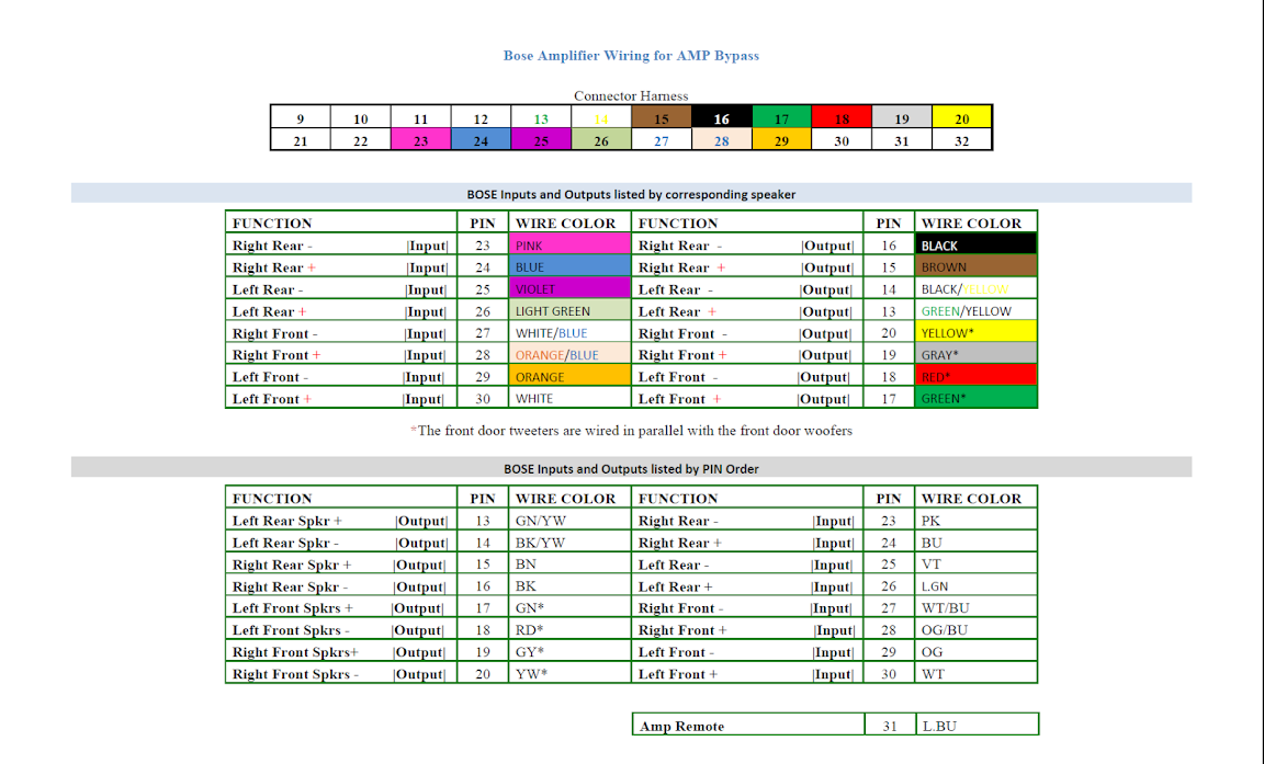
Connector:


For anyone following that may not have known for the 05 coupe the Bose Amp is on the left side of the trunk under some plastic covering. You have to remove the spare tire (or at least shift it to the right a bit) and then you remove 3 10 mm bolts with a ratchet.
Anyway I compared the wiring and it looks like my wiring table is legit except for Pin 15 which shoes to be BN which I assumed to be "brown" but in the pictures it sure looks like a shade of red to me.
Sorry for crappy pics but it was night time when i did this with a camera phone while trying to hold steady.
Look at the empty pins in the picture and the empty pins in my wiring diagram to help figure out the orientation since I took the pictures from the wrong side of the connector.
Diagram:
Connector:
Last edited by DBayPlaya2k3; 05-14-2013 at 10:36 PM.
#11
05-15-2013, 11:13 AM
Registered User
Bose Amp
Ok, you can solder but do you really want to resolder that old connector later on? I didn't so I used the inline taps. Do what you want it's your car  .
.
The recommendation to the extend the wires is spot on! bridge your wires however you see fit for the door speakers but use additional wires to run to the speaker level inputs for the amp. I would stay away from a Line Output Converter and do the speaker level inputs. Unless we are talking about a subwoofer signal.... then I would use the sub output signal on the headunit.
.The recommendation to the extend the wires is spot on! bridge your wires however you see fit for the door speakers but use additional wires to run to the speaker level inputs for the amp. I would stay away from a Line Output Converter and do the speaker level inputs. Unless we are talking about a subwoofer signal.... then I would use the sub output signal on the headunit.
#12
05-15-2013, 02:13 PM
Ok, you can solder but do you really want to resolder that old connector later on? I didn't so I used the inline taps. Do what you want it's your car .
The recommendation to the extend the wires is spot on! bridge your wires however you see fit for the door speakers but use additional wires to run to the speaker level inputs for the amp. I would stay away from a Line Output Converter and do the speaker level inputs. Unless we are talking about a subwoofer signal.... then I would use the sub output signal on the headunit.
.The recommendation to the extend the wires is spot on! bridge your wires however you see fit for the door speakers but use additional wires to run to the speaker level inputs for the amp. I would stay away from a Line Output Converter and do the speaker level inputs. Unless we are talking about a subwoofer signal.... then I would use the sub output signal on the headunit.
So you cut the harness and just used male and female taps to connect the inputs and outputs?
If so were there any issues with quality.
For this stage of the project I dont plan on buying an amp but when I do I was going to just extend the wires (as suggested) that way I would not have to run we wires to all the speakers (except for the sub which would be easy).
Do you have any tips on good stealthy places to mount a small amp?
I dont think I can use the stock location as the JL Stalthbox looks like it takes up that whole location.
#13
05-15-2013, 04:50 PM
Registered User
Do not cut
So you cut the harness and just used male and female taps to connect the inputs and outputs?
If so were there any issues with quality.
For this stage of the project I dont plan on buying an amp but when I do I was going to just extend the wires (as suggested) that way I would not have to run we wires to all the speakers (except for the sub which would be easy).
Do you have any tips on good stealthy places to mount a small amp?
I dont think I can use the stock location as the JL Stalthbox looks like it takes up that whole location.
ok can't upload atm so here's a link
http://www.google.com/imgres?q=WIRE+...4&tx=125&ty=78
Holy crap that's a long link, sorry. Anyways, you place a connector on each wire coming from the harness. BEFORE clamping it down you insert a seperate wire that will link the output/input wires. If you can wait til you talk to me on Friday I'll help you out.
Damn Wrathernaut I really need to get this damn tutorial done....

#15
05-15-2013, 06:23 PM
Registered User
Taps
I have it done that way, with the clips, and I don't have any issues. It really comes down to what you want to do. I wanted to use the clips so I could just snip snip and plug it back in incase I wanted to sell and didn't have time to unsolder etc. I may go back and redo eventually but as far as sound goes, no problems here.....