When you click on links to various merchants on this site and make a purchase, this can result in this site earning a commission. Affiliate programs and affiliations include, but are not limited to, the eBay Partner Network.
Did the testing with the gauge, the FSM states it should look exactly like the picture.
Picture shows gas at half. This obviously isn't half, close but not half.
Cluster is back from repair. When I test it in self-diagnosis mode it looks identical to what TurTLe posted in his pic. However, I did pull the needle and try to calibrate it before sending it off for repair. Should I pull the needle and put it at half then fill? It's reading in regular mode around the same as the test, which is where I think it should be. Maddening!
I'd put the cluster in self-test then set the needle exactly where it should be while testing. If you need a reference pic for a V35 with diagnostic mode on I could go out and take one.
That's exactly where my needle was during the self-test (2 marks below half). And when I put it back together I moved the needle to the middle during the self test like instructed in the manual. Now my gauge reads high by the amount I moved it. Over full when full and a quarter tank when empty. I recommend anybody doing the cluster fix to do it when you have a know quantity of fuel in the tank (like full). So you can plug the cluster in before you put it all back together and confirm you put the needle in the right place. You're doing that now but you're not certain of the fuel level in the tank. Go fill it up and make sure where you put the needle reads full correctly before you button it all up. I predict you're going to need to put it back below half like it was for it to read correctly.
That's exactly where my needle was during the self-test (2 marks below half). And when I put it back together I moved the needle to the middle during the self test like instructed in the manual. Now my gauge reads high by the amount I moved it. Over full when full and a quarter tank when empty. I recommend anybody doing the cluster fix to do it when you have a know quantity of fuel in the tank (like full). So you can plug the cluster in before you put it all back together and confirm you put the needle in the right place. You're doing that now but you're not certain of the fuel level in the tank. Go fill it up and make sure where you put the needle reads full correctly before you button it all up. I predict you're going to need to put it back below half like it was for it to read correctly.
I think you are spot on, unless I still have an actual issue other than the cluster, which seems impossible at this point. The FSM has to be off according to your experience. Especially since it's just a picture representation with no actual values. I'm going to drive it for a while as I estimate it at between half and a quarter tank based on the last fill up and mileage. If it continues to move to empty I'll at least have hope. Then I can fill up and revalidate. Otherwise, this thing is beyond resolving?
Alrighty then. Here's the wrap up post from my fuel gauge issue, which I am happy to report is FINALLY fixed. Confirmed by running two full tank to empty cycles complete with low fuel light. Here's the breakdown of what I did. It all started with a check engine light that threw a P0462, which all references recommend replacing the fuel senders in the tank. I opted to clean them and reset the check engine light. That's when the gauge really went "into the tank" (no pun)! Thinking that the cleaning didn't work or made them worse, I purchased 2 new senders and replaced the old ones. Gauge got even more weird at that point and the check engine light came back. From there, I opted to re-solder the resistor contact points on the cluster board that are chronicled in this thread. That didn't work either. Last resort was to send off the cluster to be repaired via eBay for $89. What a giant pain in the *** to track down and all of the in between troubleshooting. To anyone that runs into this issue, I feel for you. $200 for new senders and around $125 for the cluster repair and I'm back in business with a working gas gauge. I more pissed about the amount of time I spent versus how much it cost. Thanks to everyone that helped me along. Good luck y'all! This thread should definitely be a sticky.
I have the same problem but my check engine light is on says low out put I been driving like this for 6 months I plan on replacing the fuel pump hope fully that solves the problem
You guys are awesome! When I have time I will try this. I've had P0462 code popping up every other time I fill up for 6 months on my 06' G35x, and for a year or 2 before that the fuel gauge went up and down through out the drive. Now it never goes below 3/4. I'm so glad I just put up with the gauge till now so I don't end up buying new sending units if I don't have to. Thank You Riche,Jddice89
Last edited by Skateinthesun; Feb 6, 2020 at 07:12 PM.
So, just to add to the conversation... I have this issue with my FX50. Replaced both sending units and fuel pump at the dealership. No change. Took my cluster to ezelectronics in NJ to get it repaired, still doesn't work, although I'm quite dissatisfied with their work. Not only is my fuel gauge still not working, now my exterior temperature is blank, and I've lost the ablilty to reset the milage in the center cluster. Button does nothing. I know the button is good, as it works for other functions.
I'm in Jersey, so I'm going to take it back to them to get it repaired correctly. (Luckily they didn't give me the black electrical tape fix like someone else on the forum) I guess they learned you didn't need to drill the cluster.....
Honestly, this car is a giant nightmare. After more than $1500 at the dealer throwing parts at the problem, nothing was fixed. When they told me to replace the IP, I balked, since I didn't want to spend another couple grand when I felt they were just throwing parts at the problem.
I've had 2 FX45's, and a G37 Sedan with no issues whatsoever. This whole ordeal has completely soured me on Infininti.
Just thought I'd vent. I'll let you know if the second IP fix works.
Cheers
You spent $1.5k on a fuel gauge that is off? yikes lmao
So I have used two different people on eBay (the one in NJ mentioned above and the one in Texas) to fix a cluster and both did not do a very satisfactory job in my opinion and I have found that the solution to fix this problem and some other problems like dim led lights (very common with the odometer LCD display) are quite simple if you know how to carefully remove the cluster from the car, disassemble it correctly and have decent soldering skills, which neither of the other guys seem to possess, in my opinion after inspecting their work. I also don't like people taking advantage of other people's troubles and pains when they know the fix, but will not share it with the thousands if not 100 of thousands G35 owners having the exact same problem because Infiniti / Nissan had obvious manufacturing problems with their clusters. I will not go into the details about their work, but I can tell you based on my experience that both did not seem to know their way around the G35 cluster as you would expect and based on their claims within their postings. If you want to tackle this on your own read on because I will tell you the exact resistor contacts that you should inspect and re-solder. I am not going to go through all the specifics on how to remove the cluster from the car or disassemble the cluster because there are videos out there that already cover those two items. I am going to show you the cluster's circuit board and the soldering locations. A few notes first though, you will need the following tools before you get started:
phillips screwdriver (used to disassemble the cluster)
fine flat trim tool to separate the plastic gauge material from the board (flat head screw driver will work also if you are careful)
good soldering iron with a very small tip (and steady hands)
a magnifying glass because the soldering points are very small at least the led odometer ones are.
So here's the moment you have all been waiting for so lets get right to the point.
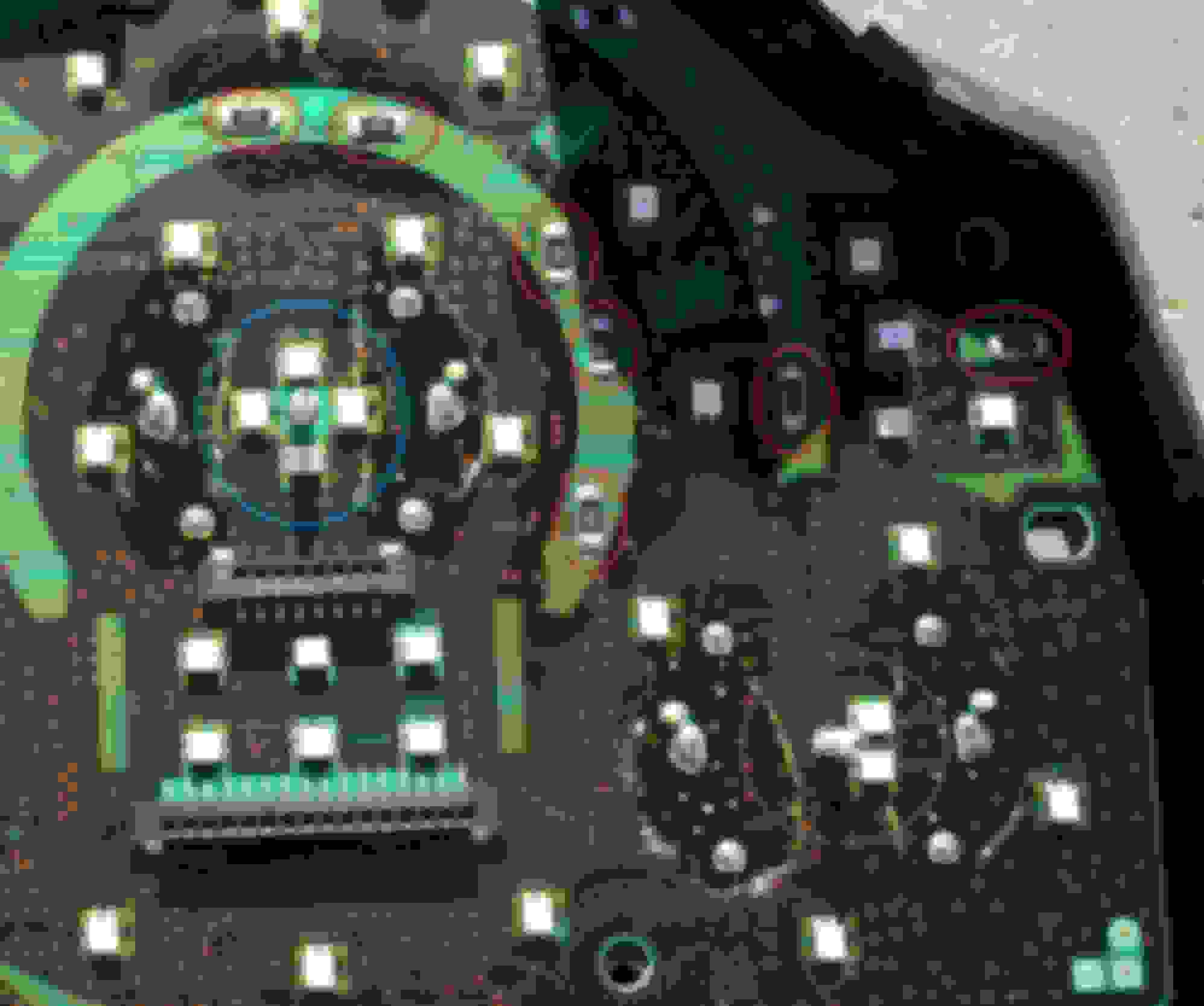
Here's a picture of the front right side of the cluster board (2006 G35). All the points circled in red show the resistors where the solder joints can go bad and separate from the board causing the erratic problems with the fuel gauge. As a reference I have circled the MPH gauge motor in blue and the fuel gauge motor in purple.So there you have it, very simple and easy, but not for the faint of heart because you can easily ruin a cluster if you do not have the proper patience and skills.
So now lets get to the led lights for the odometer display issues - dimming, flickering, or just completely not working.
This is the back left side of the board, which is a little bit easier to get to because you do not need to remove the two LCD displays to fix it. On the back side of the board on the bottom left side where you see the pins from the odometer LCD display sticking through you will see a lot of small (smaller than the front side shown above for the fuel gauge fix) resistors that need to be re-soldered to fix the cold joints. All the resistors in the red rectangle should be re-soldered if your odometer display is not lit up like it should be.
Soldering hints: Because one side of the resistor may not be attached (the very problem described here), it is possible for the resistor to move / shift while trying to re-solder it. It is best to apply light pressure and maybe even hold the resistor with a small tool that would not damage the resistor while trying to solder the first side you are working on. This happened to me twice while I was repairing a board so I started to hold them in place when re-soldering the first side. It shouldn't happened on the second side because your new soldering joint (if done correctly) will hold it in place.
After you are done, you and your G35 will be able to enjoy the good life again.
If you need the proper method for disassembling the cluster, let me know so you don't end up doing stupid things like the person in Texas who thinks you have to drill through the plastic to remove the screw underneath it. like in the following picture: It may be hard to see in the picture, but it is quite obvious when looking at it directly. He drilled through the plastic cover to unscrew the screw underneath it. This is not necessary because you should remove the whole plastic display piece then you unscrew the screws to get to the board. He obviously was clueless on how to work on the G35 cluster. He then covers the hole with black electrical tape like that is professional work, not. Please don't do stupid things like this idiot.
I hope you enjoyed this post and good luck, if you decide to tackle this on your own. I spent way too many hours and money trying to research and fix this problem so I thought I would share it so you wouldn't have to go through the same thing I went through.
I own a 2013 g37XS sedan and I�m having the same issue right now. Not quite as bad as yours but I�m experiencing the inconsistent fuel readings. I put 20L in three days ago and somehow I have 3/4 of a tank when driving 80-100kms a day. Car has 100,000 kms on it and it hasn�t been great this far
Alright folks, long lived thread. Was searching for the source of this issue for a long time with many threads being unresolved which is the most annoying thing. So on that note i wanted to add my two cents that the soldering of the resistors in this thread worked for me. I had pulled the fuel floats and cleaned those with still a wonky gas gauge. Up here in canada with temps varying -30C to +30C i can see why these solders just dont hold after many years. With a cracked solder and temperature fluctuations it makes total sense why the guage wouldnt know what to read. There are youtube vids on how to take apart the dash to the circuit board, just make sure you take a picture of your dash in test mode so you know where to place the needles after installing.