
$5 Door Lock Motor (Actuator) Fix


[QUOTE=pythonjosh;5631075]This part is critical. I have noticed in some installations that when you screw in the lower 2 screws that secure the door lock cable, that it can lift up the pin pretty high (sometimes) causing it to pop out of the hole and needs to be readjusted.
After I screw those in I always run a little endurance test and manually switch it back and forth to make sure it will stay in the hole.
In your case, it is for sure that the pin came out of the hole and the screws are not securing the door lock cable any more.
+1
That happend to me a few time while testing mine when all hooked up.
Could also possibley the clamp cracked from over tighting and finally gave out.

Im gonna write up what i found when doing this... Hope these tips help others and avoid going through what i did. After getting the door off finally i did i 110% this time.
1. Route your wires you spliced into (purple and blue) under the BOSE speaker.
Tip: Put a bit of tape on the blue wire so you know which is which if you used the same coloured wires.
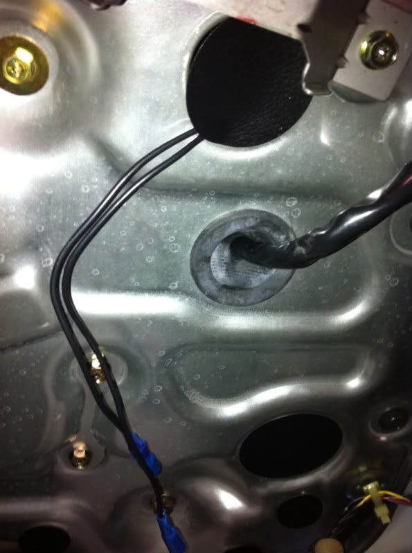
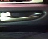
2. Take off the inner door handle, you want to drill where the smaller hole is
Tip: have the bottom of the hole line up with the bottom of the existing cable hole. Mine could have been a tiny bit closer to the bigger hole (which was a mistake) dont drill the big one..
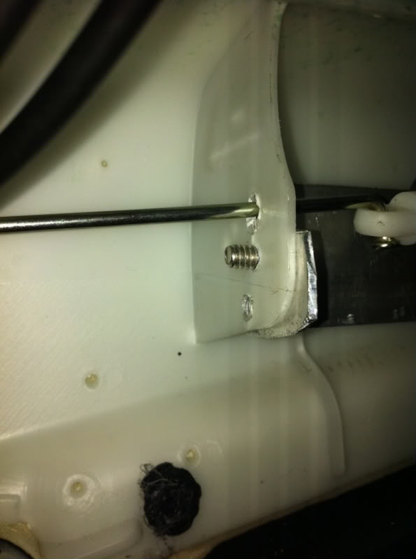
3. Now drill a hole in the closest plastic tab to the inner door lock.
Tip: The hole should be 2cm high, 1.5cm in.
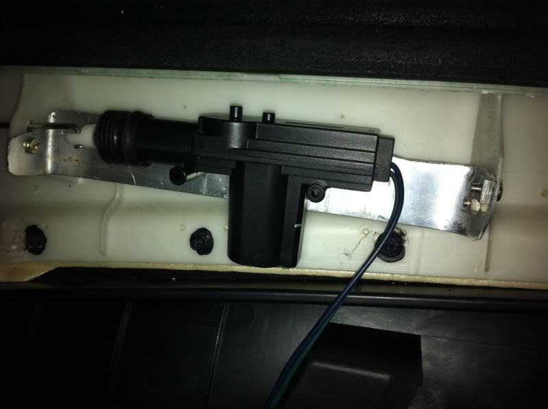
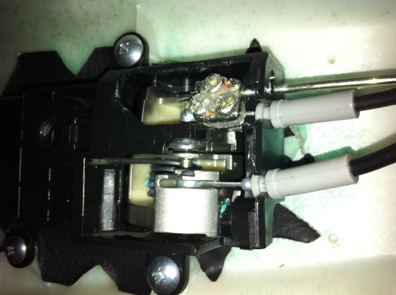
4. Mount the Actuator
Tip: height should be around 2.5cm from the top of the door trim. Also put two screws on angles at the back to stop the brack from twisting when unlocking and locking.
5. Tape lock the 3 screw bracket
Tip: Pull the tape as you put it on, too much and it will bunch up
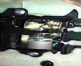
6. Mount the door lock cable FIRST then run the actuator rod into the bracket.
Tip: The way you mount it right is all the difference
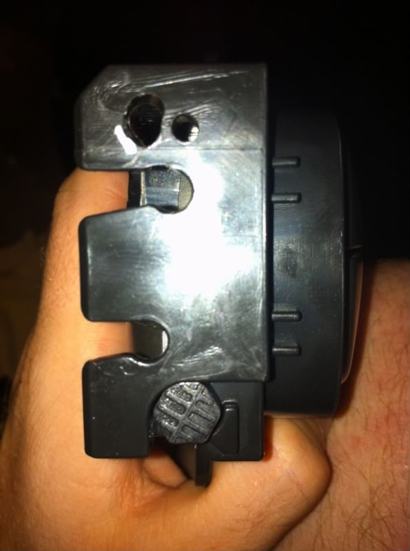
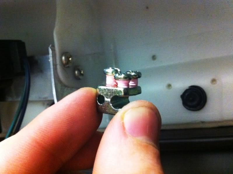
RIGHT way: Notice the L shape pin is push into the hole
WRONG WAY: See the pin is sitting out, DONT install like this
This bit is sort of Step 6a...
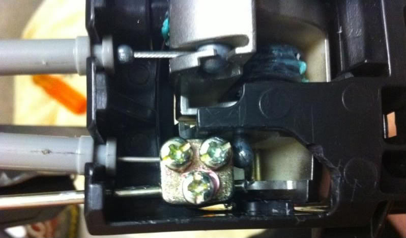
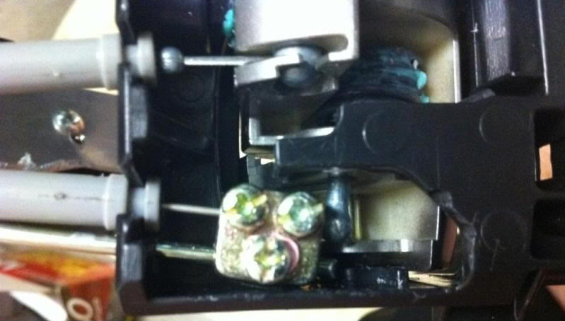
Once you have the locking cable with bracket attached put that little L pin in the door lock bracket and click the cable in the hole. Now you will have to take the Actuator off again so you can put the rod in the end (i forgot to measure how much i cut off) and then put the rod through the first hole in the white tab and then through the black hole you made in the inner door lock bracket.
Tip: As you put it through the hole you then put the rod through the top 3 screw bracket. DONT tighten yet. Hook up power to the actuator and see how far the rod goes in the unlock position, if clearance is good Now use a flat blade screw driver to tighten that last screw. Now test manually and with your remote heaps of times. Once right silicone that MF. Put some on the screws and some under where that L pin is.
Your done!
Just make sure the actuator can EASILY open and close, you dont want ANY struggle.
If done good yours should look like these videos. CLICK THEM TO PLAY
Locking mechanism: See how strong the actuating is, it fully opens and closes with the L pin always in the hole. I am trying to show that the bottom of the pin is visible at the bottom of the bracket.
Actuator Mount: See There is very little flex when it actuates

Inside door lock: Again see how it fully locks and unlocks, you dont want it to only move half way..
1. Route your wires you spliced into (purple and blue) under the BOSE speaker.
Tip: Put a bit of tape on the blue wire so you know which is which if you used the same coloured wires.
2. Take off the inner door handle, you want to drill where the smaller hole is
Tip: have the bottom of the hole line up with the bottom of the existing cable hole. Mine could have been a tiny bit closer to the bigger hole (which was a mistake) dont drill the big one..
3. Now drill a hole in the closest plastic tab to the inner door lock.
Tip: The hole should be 2cm high, 1.5cm in.
4. Mount the Actuator
Tip: height should be around 2.5cm from the top of the door trim. Also put two screws on angles at the back to stop the brack from twisting when unlocking and locking.
5. Tape lock the 3 screw bracket
Tip: Pull the tape as you put it on, too much and it will bunch up
6. Mount the door lock cable FIRST then run the actuator rod into the bracket.
Tip: The way you mount it right is all the difference
RIGHT way: Notice the L shape pin is push into the hole
WRONG WAY: See the pin is sitting out, DONT install like this
This bit is sort of Step 6a...
Once you have the locking cable with bracket attached put that little L pin in the door lock bracket and click the cable in the hole. Now you will have to take the Actuator off again so you can put the rod in the end (i forgot to measure how much i cut off) and then put the rod through the first hole in the white tab and then through the black hole you made in the inner door lock bracket.
Tip: As you put it through the hole you then put the rod through the top 3 screw bracket. DONT tighten yet. Hook up power to the actuator and see how far the rod goes in the unlock position, if clearance is good Now use a flat blade screw driver to tighten that last screw. Now test manually and with your remote heaps of times. Once right silicone that MF. Put some on the screws and some under where that L pin is.
Your done!
Just make sure the actuator can EASILY open and close, you dont want ANY struggle.
If done good yours should look like these videos. CLICK THEM TO PLAY
Locking mechanism: See how strong the actuating is, it fully opens and closes with the L pin always in the hole. I am trying to show that the bottom of the pin is visible at the bottom of the bracket.
Actuator Mount: See There is very little flex when it actuates
Inside door lock: Again see how it fully locks and unlocks, you dont want it to only move half way..
Last edited by R6n350GT; Jan 27, 2011 at 04:22 PM.

Registered User
Joined: Aug 2008
Posts: 4
Likes: 0
From: Providence
I did this install on both doors this weekend...so far both work great! Awesome project and saved hundreds by not going to the dealer. Thank you very much for your help guys! much appreciated.
Beats spending 300. per door for an OEM version and for which will most likely *&^%$ up again


Memeber Pythonjosh who was selling these kits a while back isnt responding (maybe he no longer makes these). Can anyone tell me what type of metal they used to make the mounting brackets and what type of wiring/connectors worked the best?
Pg 3 is where you will find what I did

What I use for the bracket is a 3/4" wide aluminum bar. Cut to 10" and bend up 1" on each end to 90�
For all drilling I use a 5mm drill bit. Drill a hole at the top of each end of the bar, then place the actuator on the bar to line up where you want to drill the actuator mounting holes.
After this you need to cut the actuator bar to 8".
For the wiring you need 2 red butt connectors, 2 blue female bullet connectors, and 2 18ga wires but to 24".
For my kits I supply one blue wire and one green wire. Blue connects to blue, and green connects to purple. This way next time you have to unplug to remove the door panel for any reason, the wire colors will match and you won't have to test if pressing lock will lock.
Thanks,
Josh

