~TunerMax's RF Controlled Colour Changing LED Project~ PIC HEAVY

Wow! All I can say is wow!
I'm sooo glad to see that someone has/is trying this. When I read that the 04's didn't have LED's I was heart broken, but its good to see a clean way to upgrade.
I'm curious though, did you end up using a scratch remover on the reverse of the gauges? And if so, did it cause those dreaded bright spots?
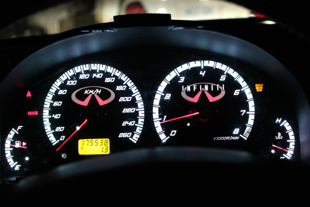
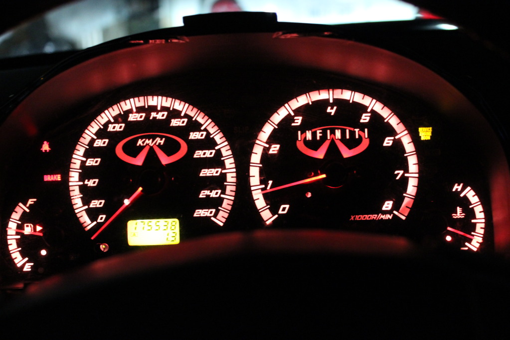
Also, the way it is set up right now, the red line on the tach is going to be lit up with the same color of the gauge. Did you think about separating that portion off and using just white LED's so that the intensity will remain constant as the color changes?
I'm sooo glad to see that someone has/is trying this. When I read that the 04's didn't have LED's I was heart broken, but its good to see a clean way to upgrade.
I'm curious though, did you end up using a scratch remover on the reverse of the gauges? And if so, did it cause those dreaded bright spots?
Also, the way it is set up right now, the red line on the tach is going to be lit up with the same color of the gauge. Did you think about separating that portion off and using just white LED's so that the intensity will remain constant as the color changes?
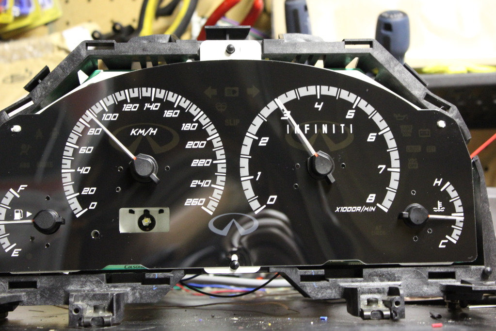
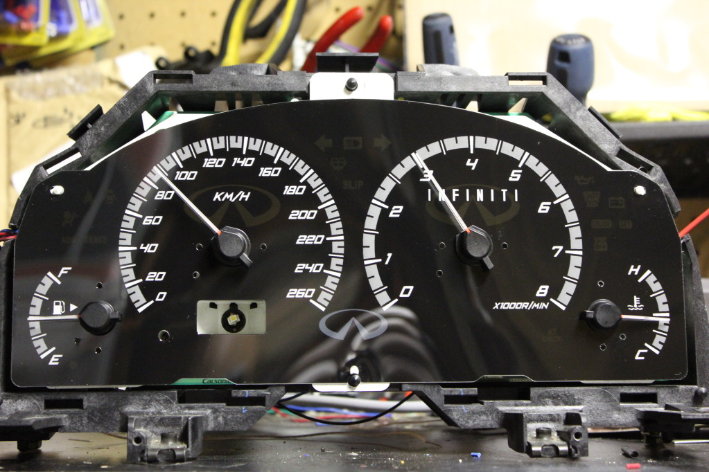
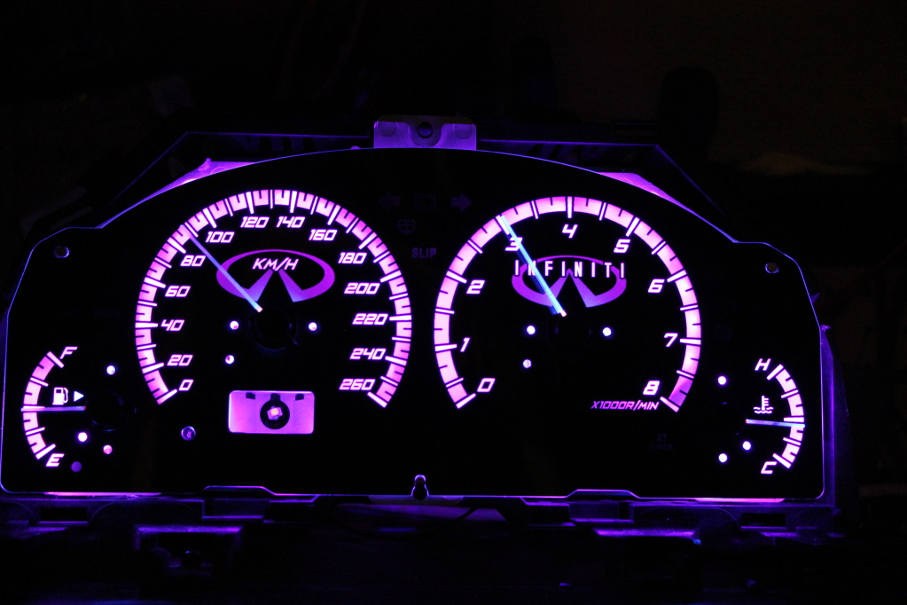
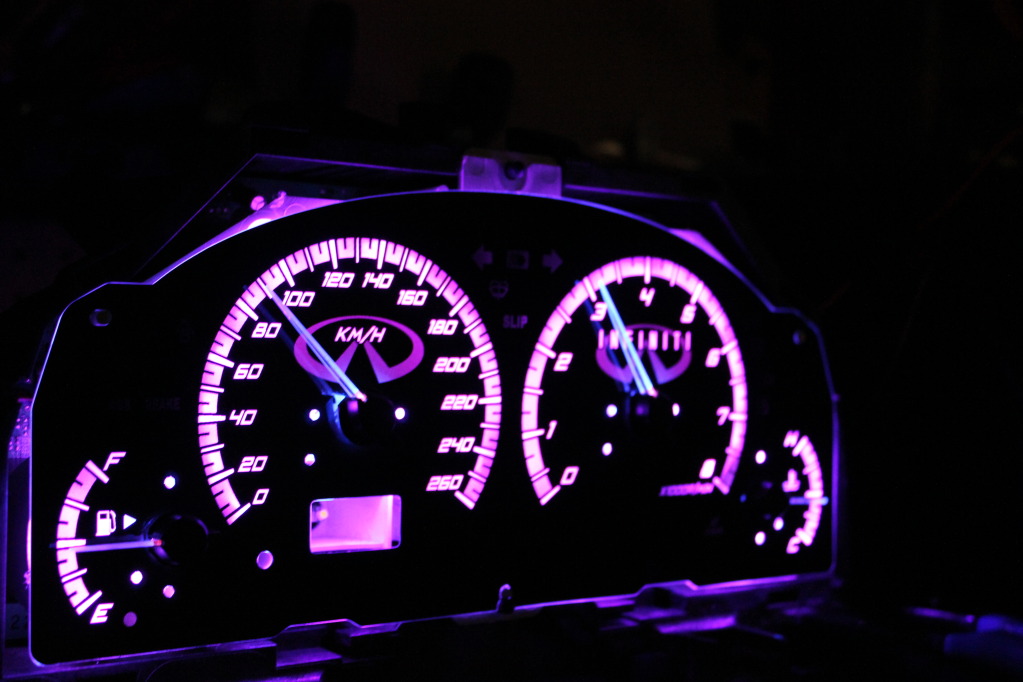
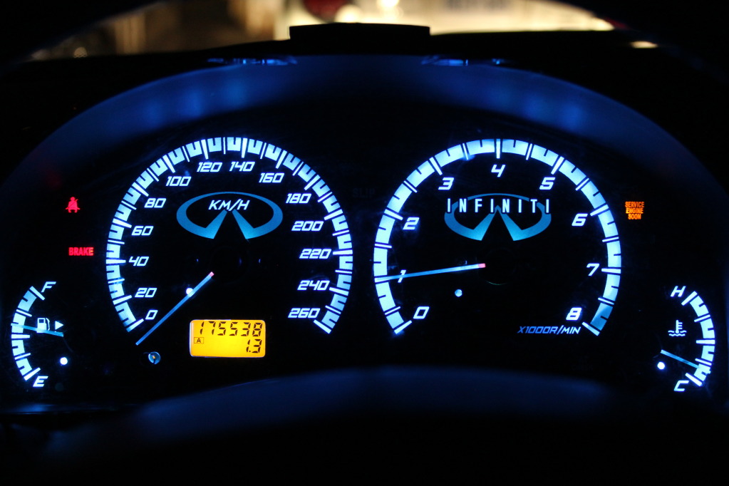
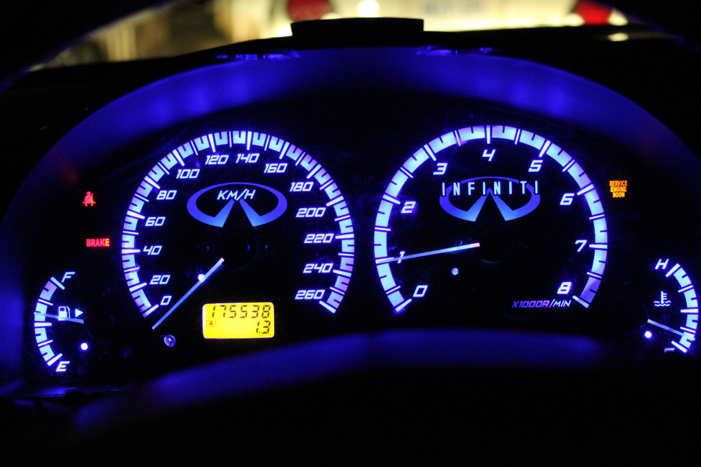
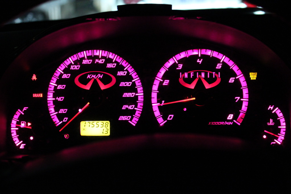
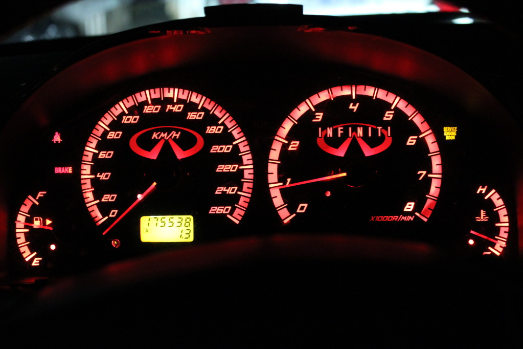
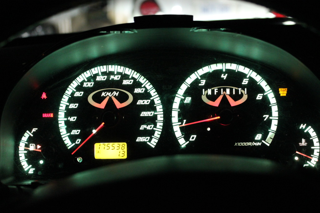
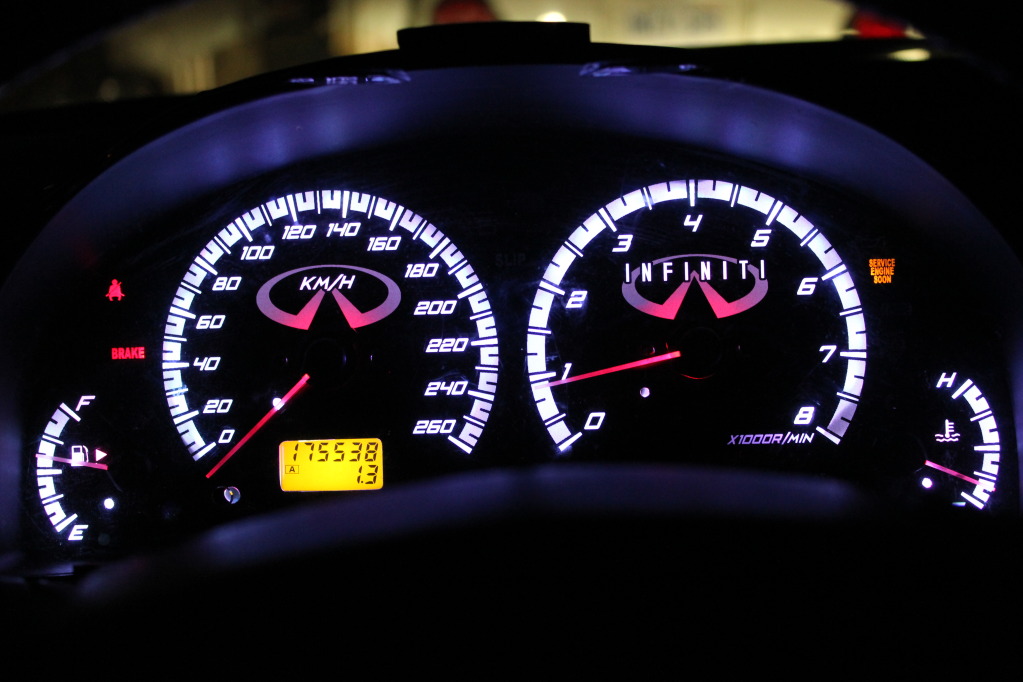
I just used 600 Grit Wetsandpaper, nothing special. Hotspotting is more pronounced whenever you remove a tinting, simply because the tinting helps disperse the light a bit. But the main cause for any hotspots is simply the position and direction of the light. Most guys use LED's, which by nature, cause hotspots. And most guys aim these LED's right at the gauge face, similar to the way the stock bulbs are. I didn't, as you can see, I aimed them at 90 degrees to the gauge face, and because the interval between LED's in the strip I used is small (gap between), there really is NO hotpots at all.
regarding the Redline, yeah, I'll likely do something with it. Right now I'm working out a custom gauge face alltogether, I decided the old one had to go, way too outdated. So hopefully I can find a way to make the tinting work all the time, I'll have to inquire.


Can't believe I'm doing this
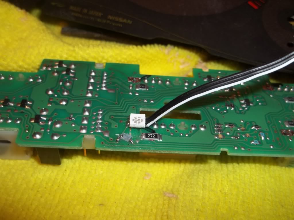
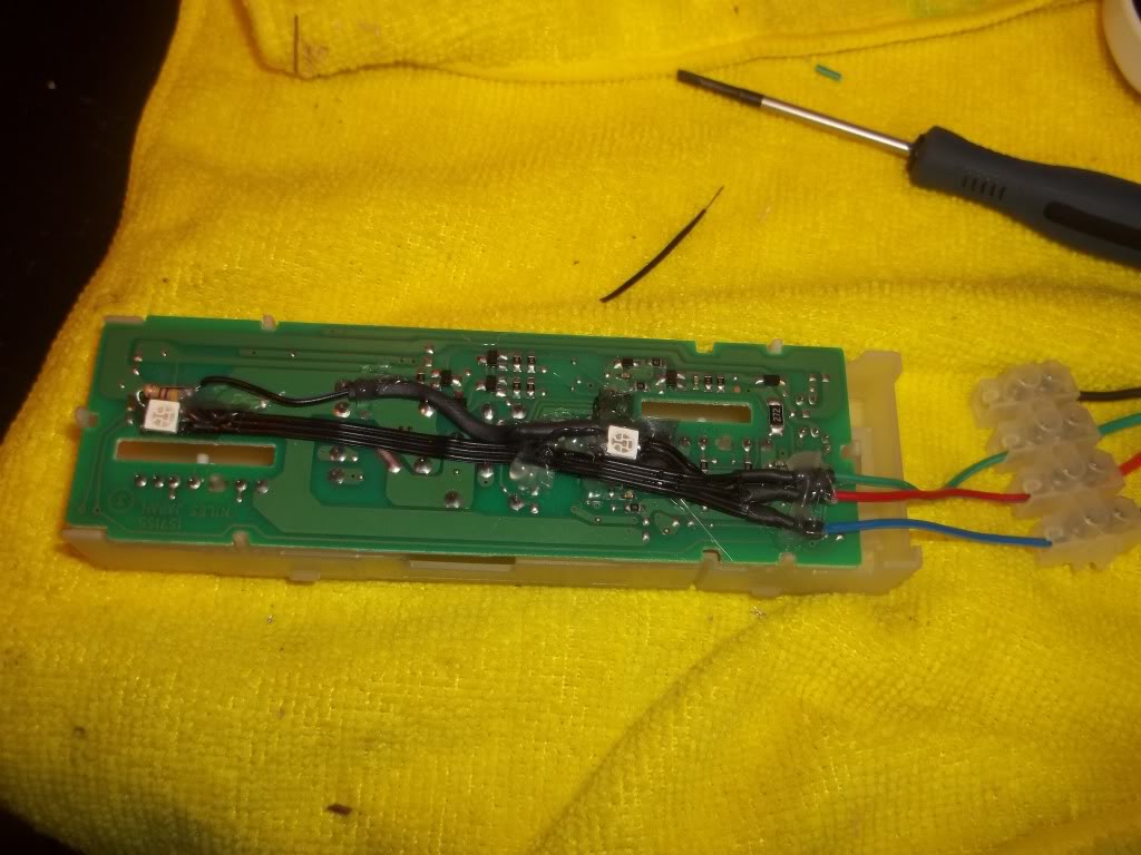
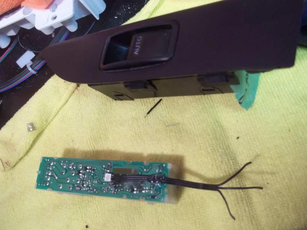
This is freaking nuts. I just spent 1.5 hours installing ONE, yes, ONE SMD into the Master window switch. Had to redo the bloody circuitry to do it. Ugh. Oh well, here we go!!! 
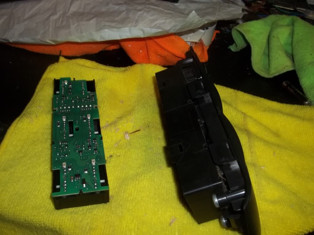
Window switch diassembled:
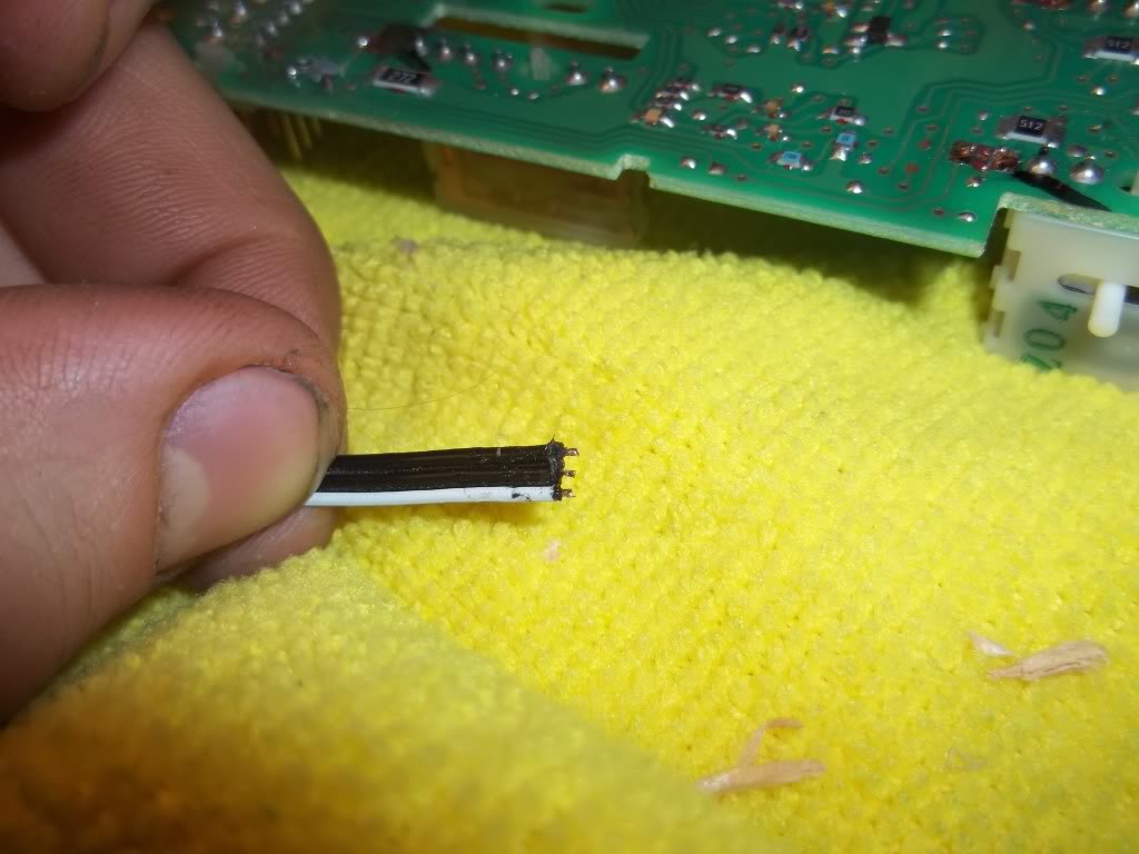
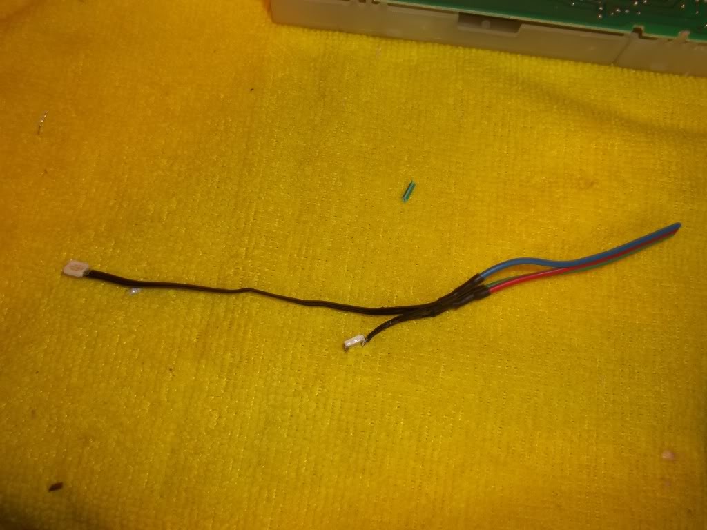
Ribbon wire stolen off an old computer I had:

OEM led's all marked:
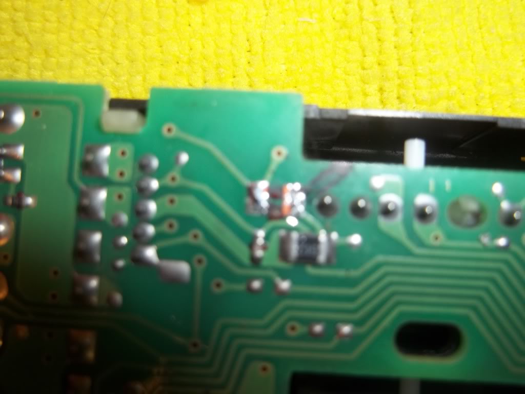
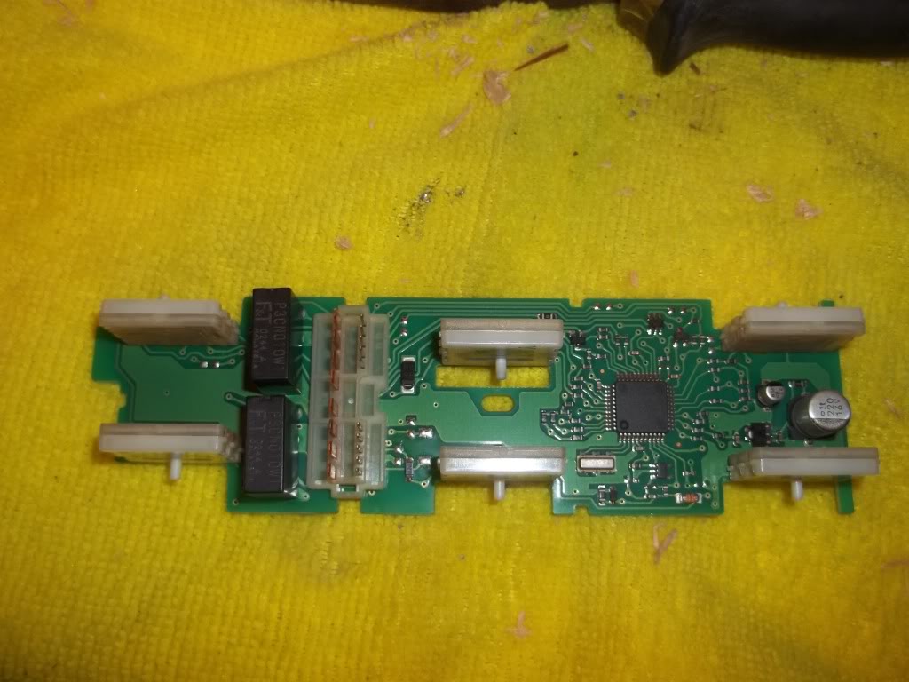
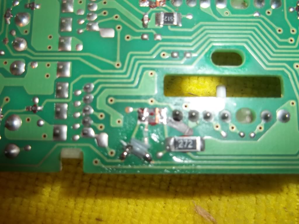
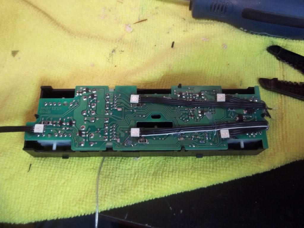
Modding the circuit board. Note now-exposed copper contacts by resistor labled "272"
installed jumper
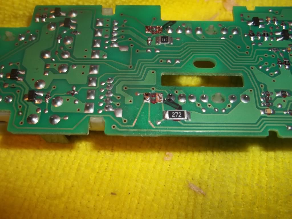
Cut feed strip, I did both, but only one cut is shown:
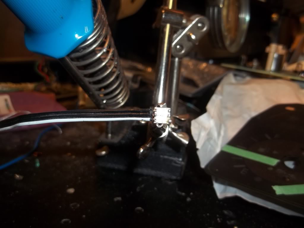
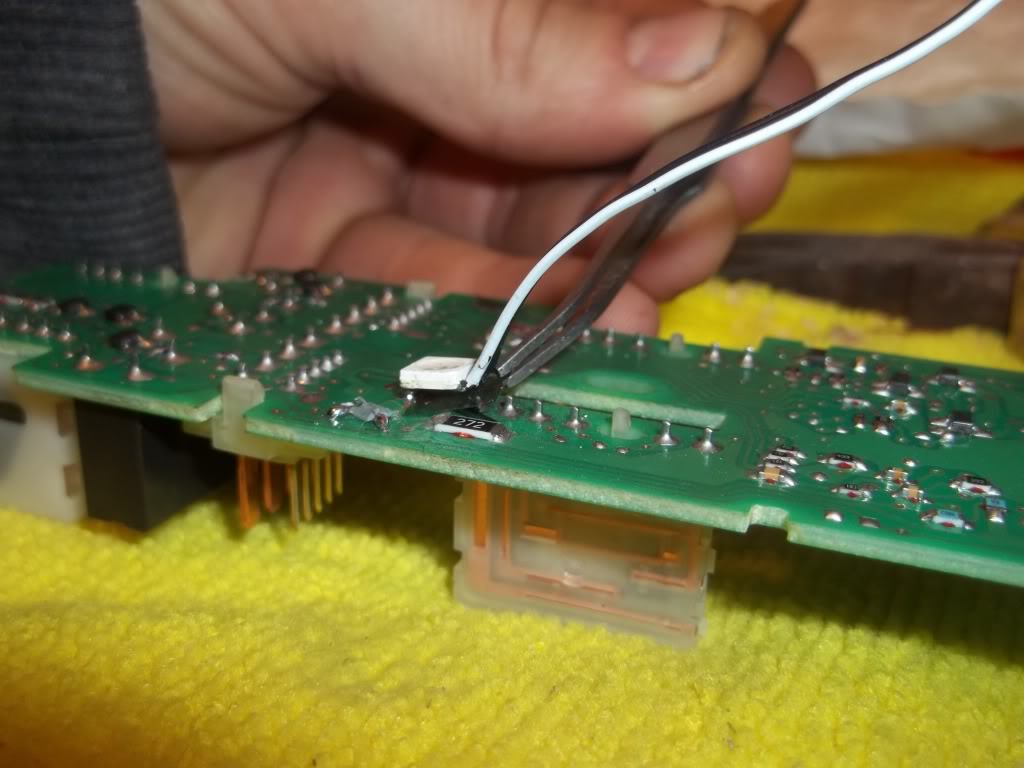
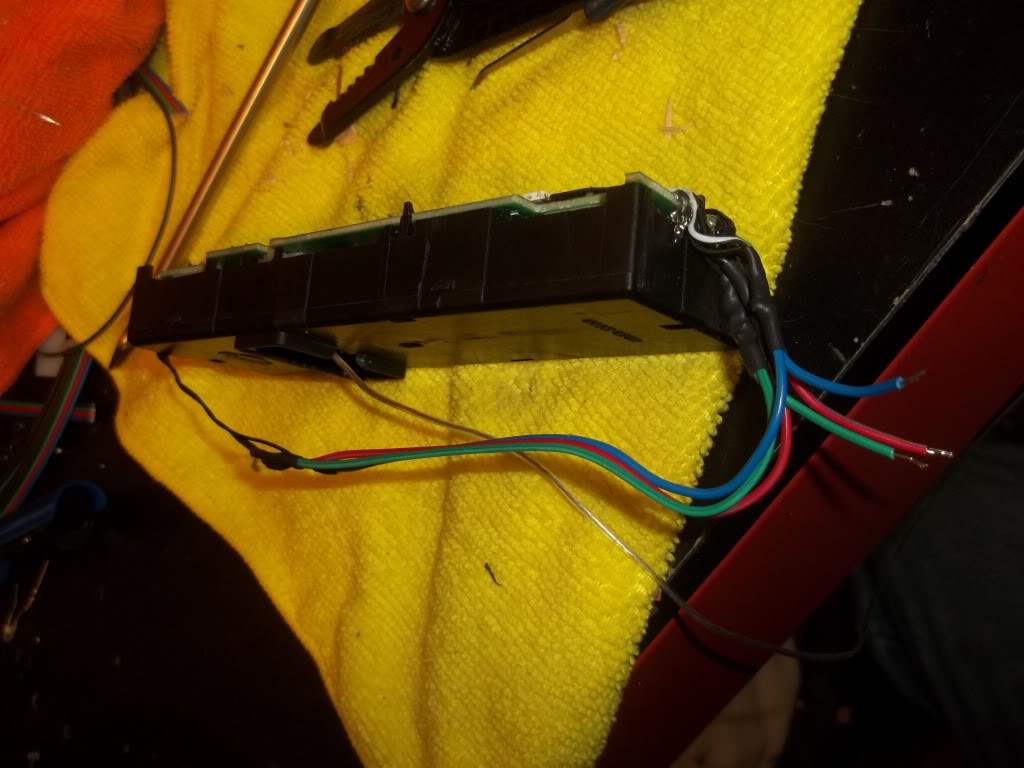
Prepping/Tinning Ribbon wire:
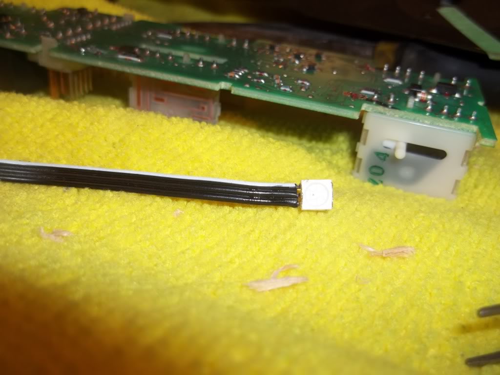
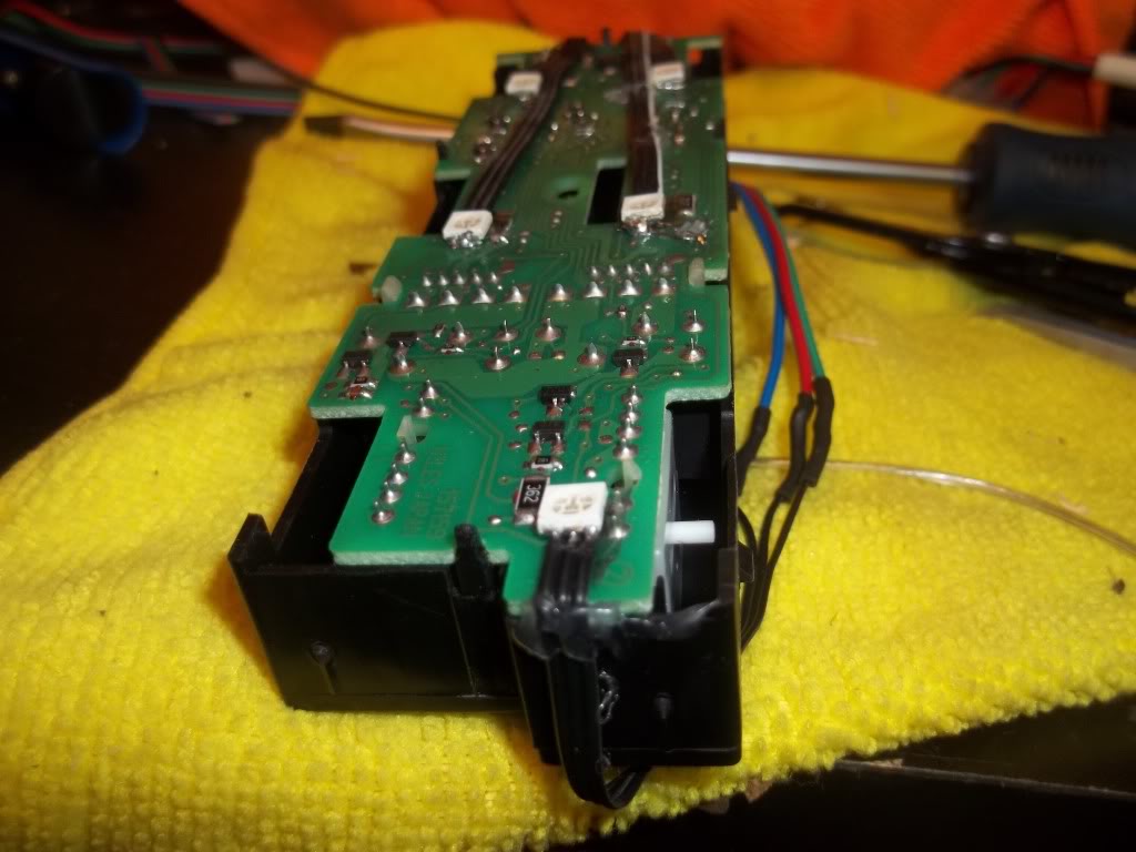
test fitting:
Used transparent vinyl in between new SMD and circuit board to prevent potential issues
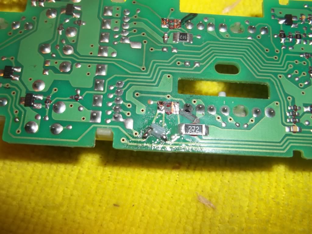
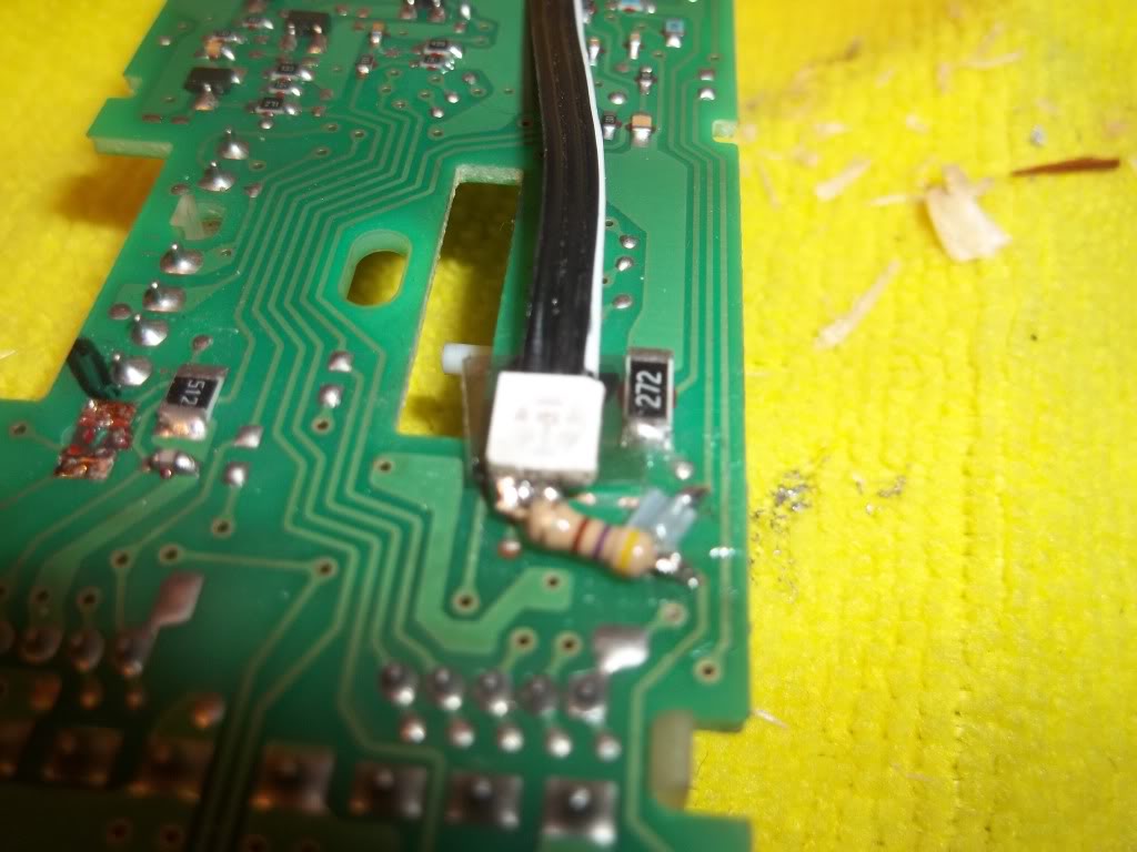
Resistor installed (it sucks that I have to install them,normally you don't have to when doing circuit boards, but I wasn't using the OEM illumination ground circuit, so I had to redo this ALS0 LOL)
LOL)
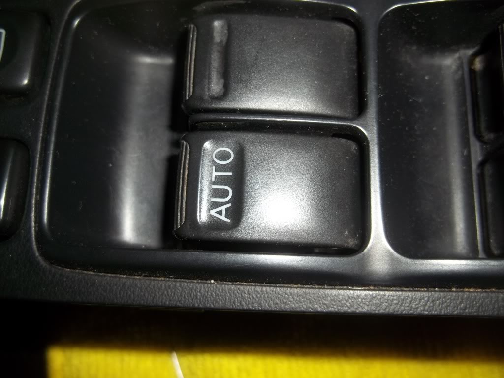
Temporarily Hooked up power to PIN #14 on Master switch, and ran grounds to LED controller for testing. Moment of truth:
Video will be live shortly:
Window switch diassembled:
Ribbon wire stolen off an old computer I had:
OEM led's all marked:
Modding the circuit board. Note now-exposed copper contacts by resistor labled "272"
installed jumper
Cut feed strip, I did both, but only one cut is shown:
Prepping/Tinning Ribbon wire:
test fitting:
Used transparent vinyl in between new SMD and circuit board to prevent potential issues
Resistor installed (it sucks that I have to install them,normally you don't have to when doing circuit boards, but I wasn't using the OEM illumination ground circuit, so I had to redo this ALS0
LOL)Temporarily Hooked up power to PIN #14 on Master switch, and ran grounds to LED controller for testing. Moment of truth:
Video will be live shortly:
Last edited by TunerMax; Feb 11, 2012 at 08:54 PM.
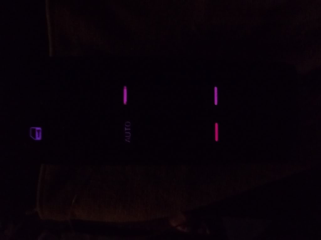
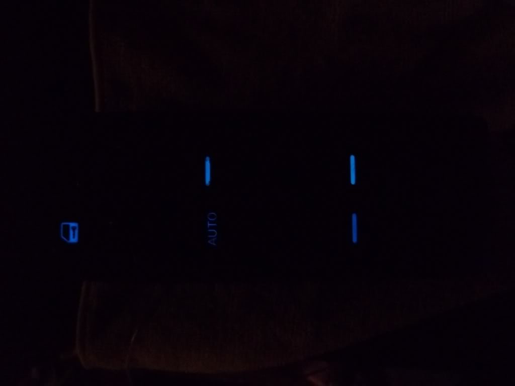
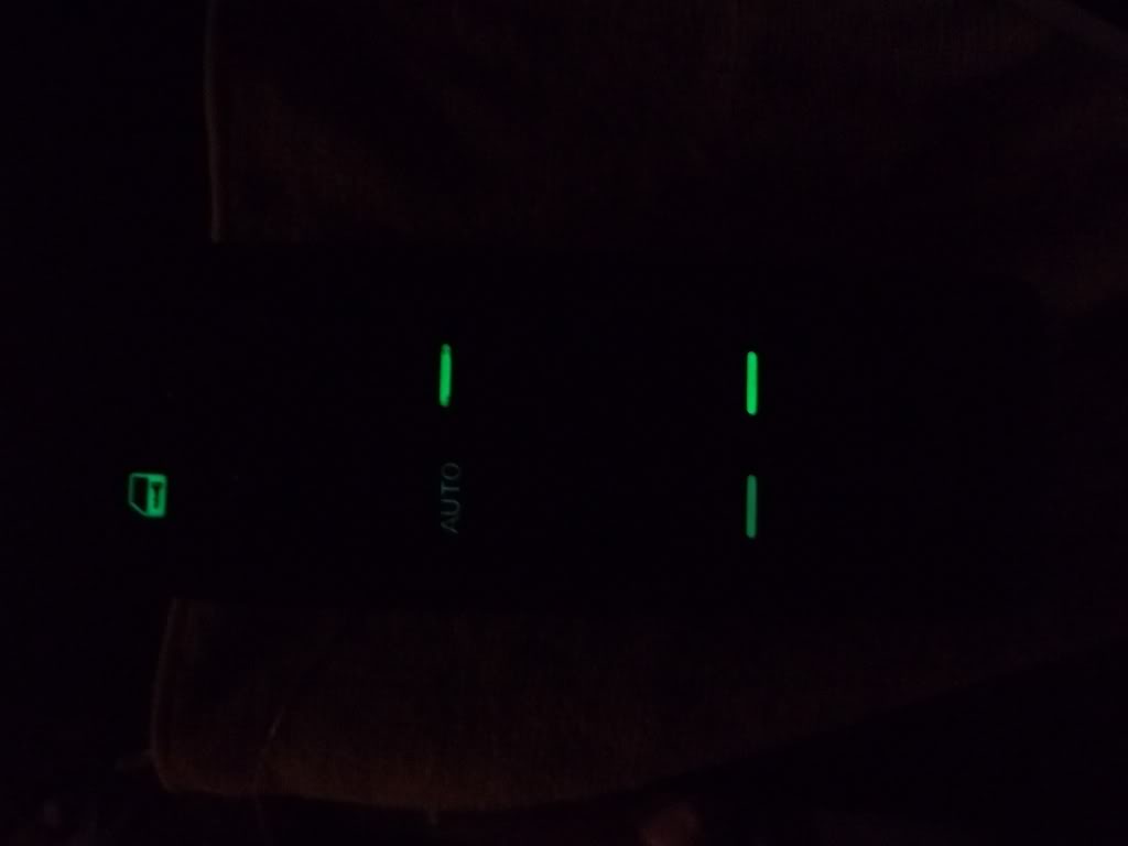
Master Switch - In progress
EDIT: There was a mix-up on the wiring for this unit, so in the pictures shown below, the lights are way too dim, I will revisit it. See next post of Passenger switch for the brightness it's SUPPOSED to have


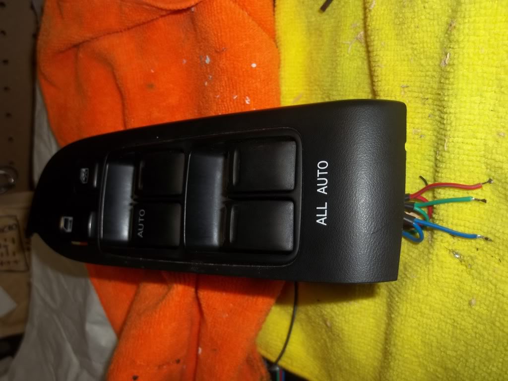
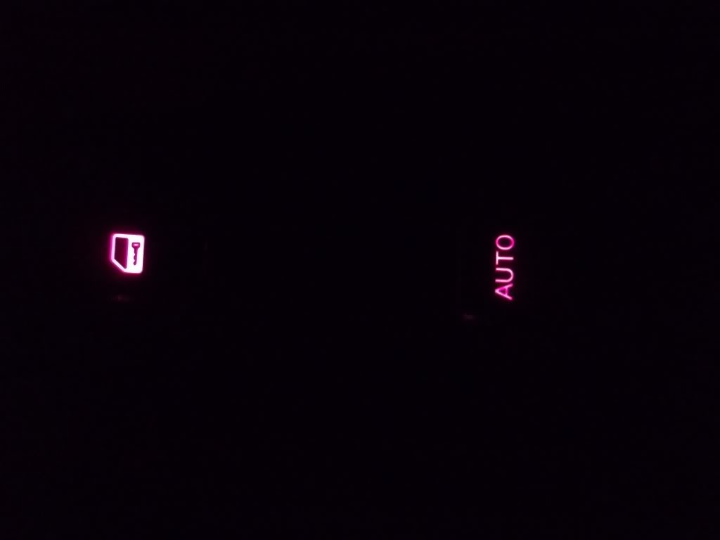
Lit up pictures turned out TERRIBLE, I'll get some more later these will have to suffice for now:
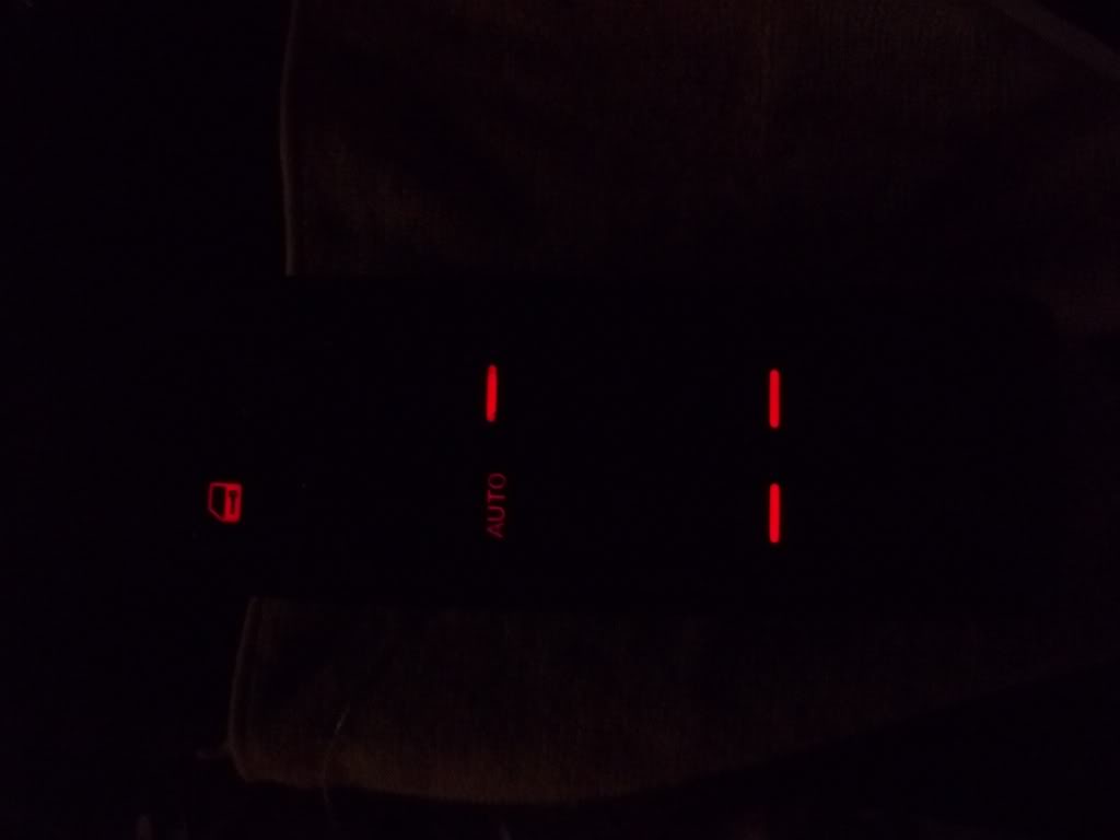
Lit up pictures turned out TERRIBLE, I'll get some more later these will have to suffice for now:
Last edited by TunerMax; Feb 12, 2012 at 10:54 PM.
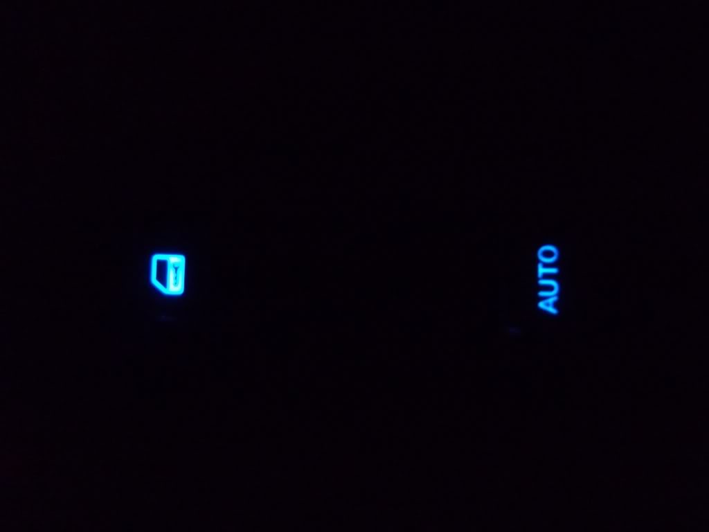
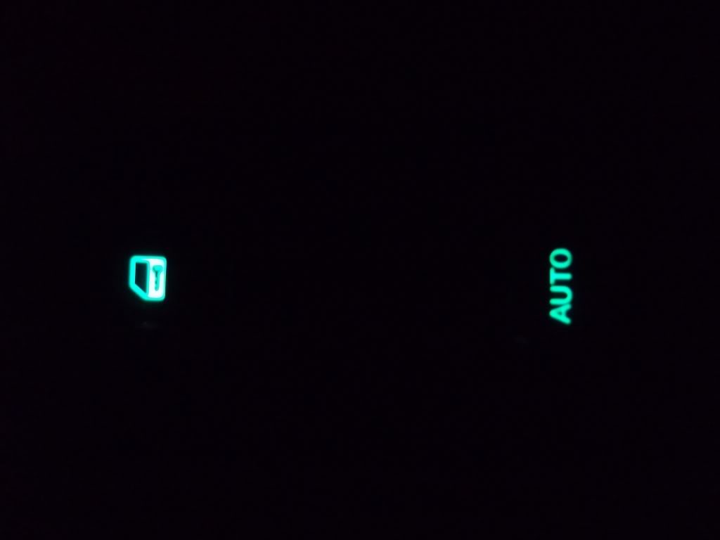
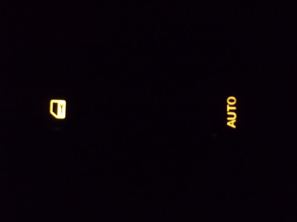
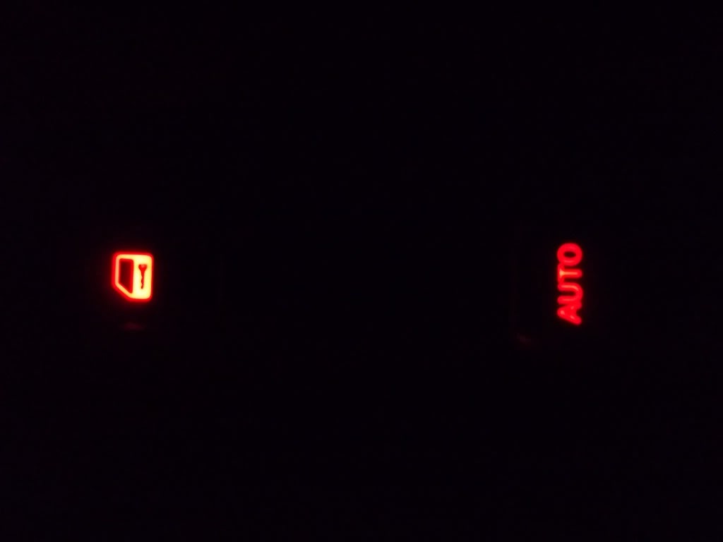
Passenger Switch done
K, the Master switch DOES have an issue. I couldn't say for sure cause it was daylight and it was the first one, but it's way too dim. I got the Passenger side done tonight and that verified it.
Here's the passenger switch, I"ll have to revisit the Master Switch to fix 'er up.
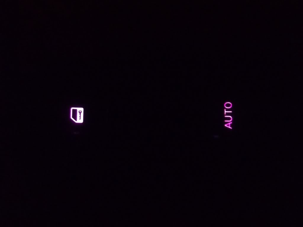
Here's the passenger switch, I"ll have to revisit the Master Switch to fix 'er up.

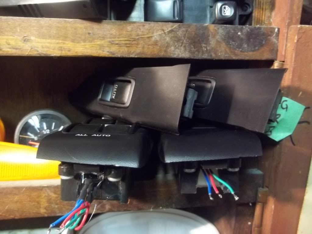
~All Window Switches Done~
Fixed the Master switch and swapped in the rear switches as well. All prepped and ready for install, here's the updated vid of the Master switch and some photos of process:

And OT a bit again but I improved my Halo idea for the reverse light:
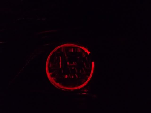
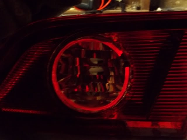
And OT a bit again but I improved my Halo idea for the reverse light:
LCD Screen experiments
I've been pretty well stuck waiting on parts, and have been very busy with other projects. But I got my testing done on the LCD screen, just need to do up the finished product now. Here's some pics of the testing procedure.
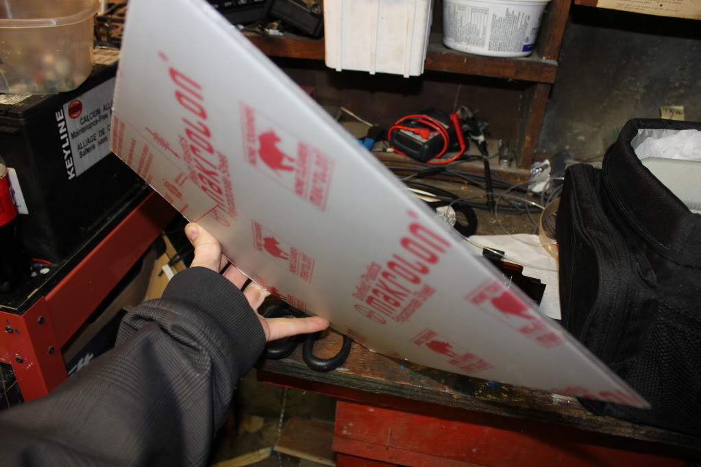
The Plan:
Use a clear acrylic light transmitting plastic to replace the stock Tinted lens, shown below:
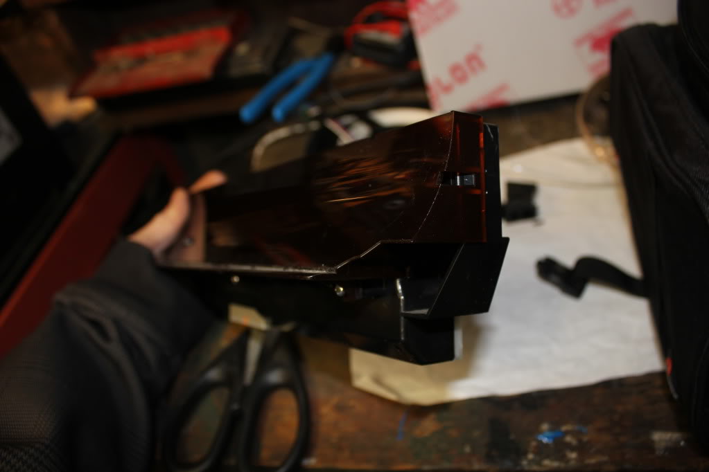
The acrylic piece:
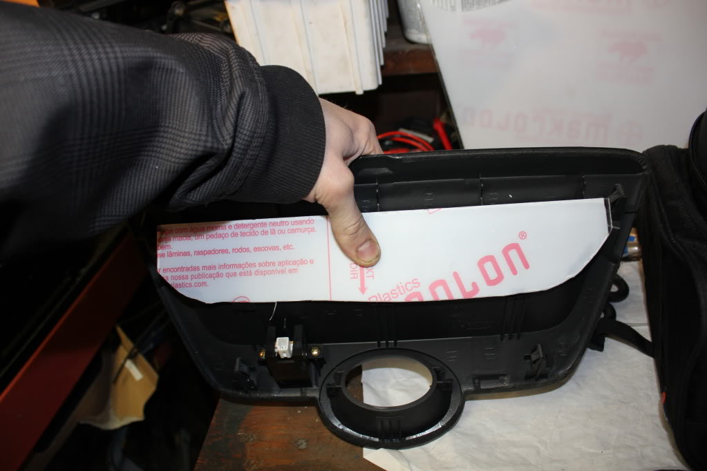

Cut and test fit:

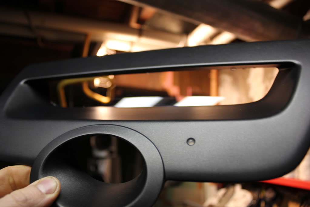
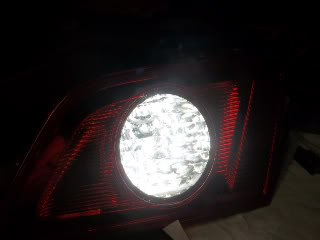
Next part of the plan, run the colour changing LED's around the acrylic, to light it up:

Turned out good.
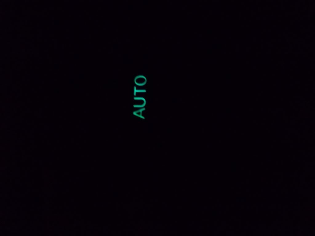
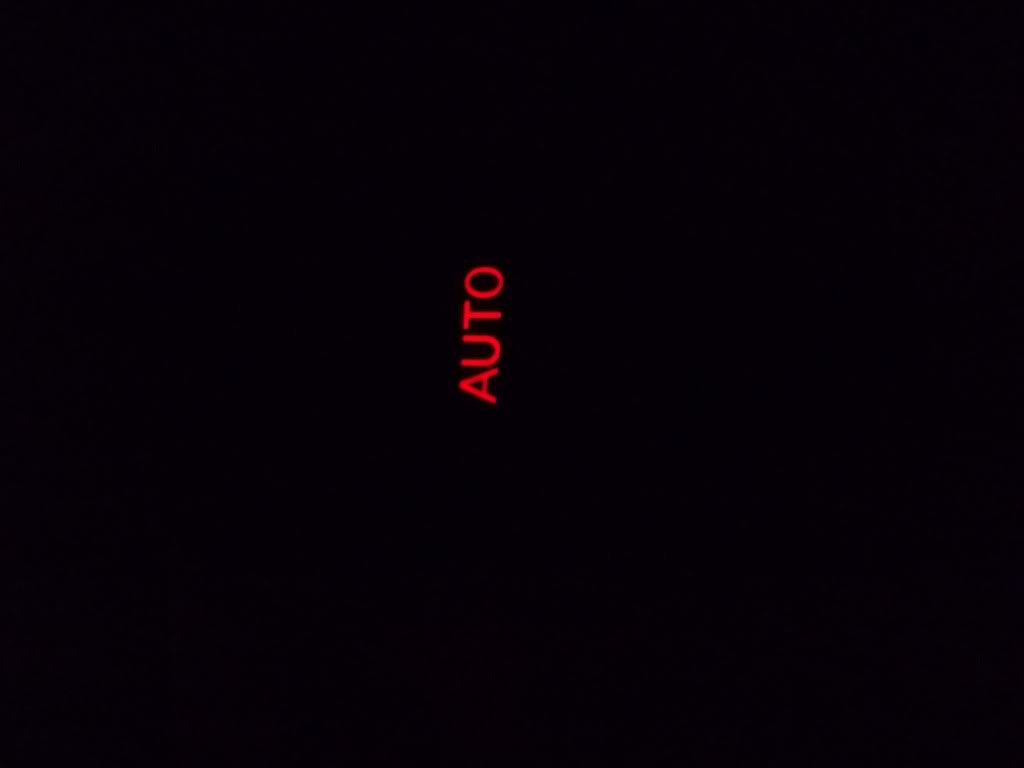
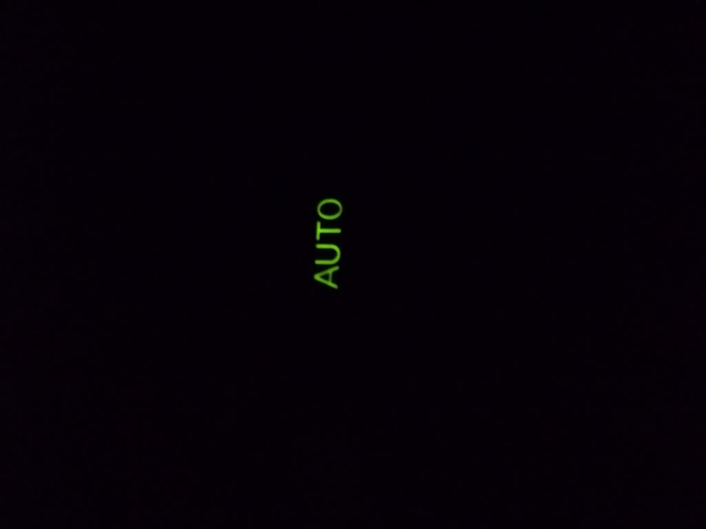
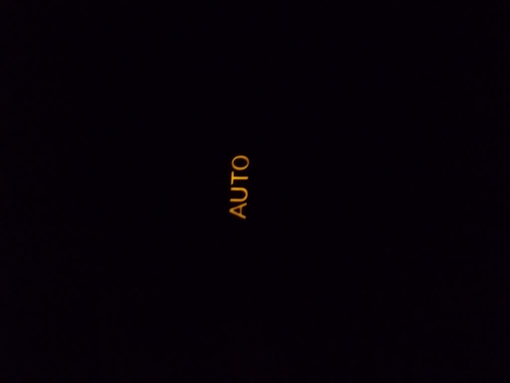
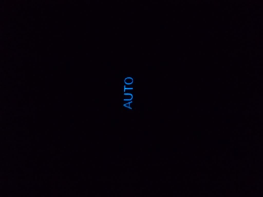
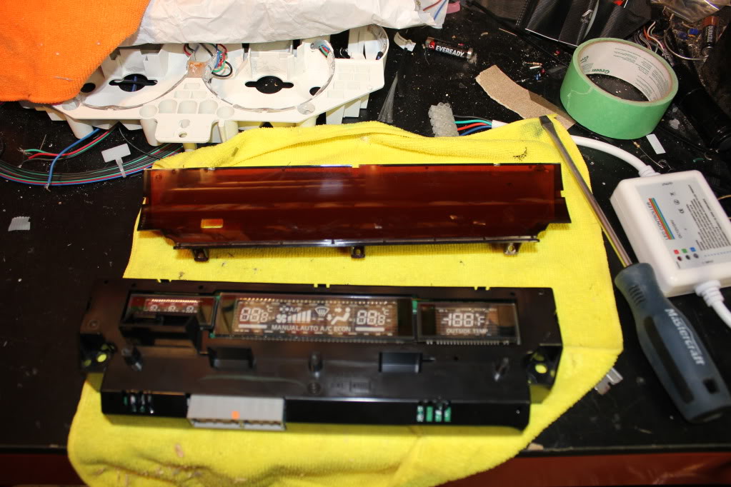
Now the other part of this plan, was complete guess work. I didn't know if the lights would work or if they'd just block the LCD out. Either way, I was making the normally GREEN coloured LCD screens WHITE:
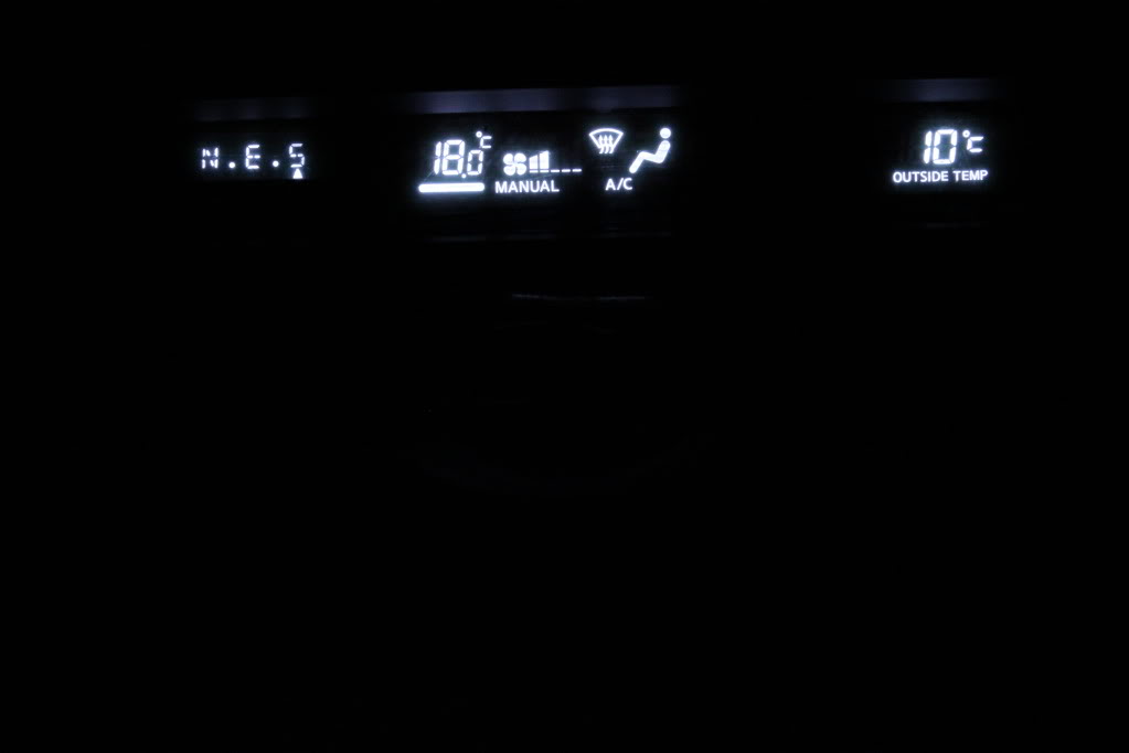
And finally, the final test, didn't take many photos, but I'm happy enough with the result. It should be obvious that this is not fully installed, and the tinting I used will be replaced with a good piece. I'll also be redirecting the LED's so they don't light up the screen at all, and I'll be tinting the portions of the LCD screen so you can't see anything but the numbers. This picture is of a VERY ROUGH first test. The final product will basically be just the normal output of the screen, in white, and then a clear lit piece that changes colours with the rest of the car's theme.
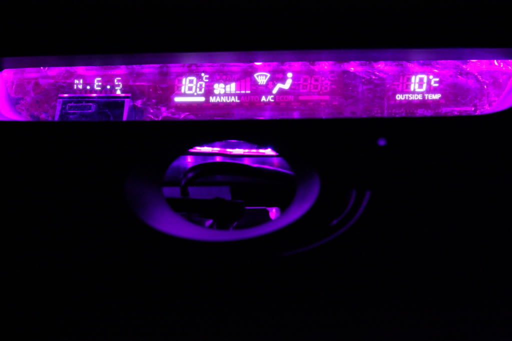
I was worried the Coloured screen would mess upt he LCD output but it actually looks fine
The Plan:
Use a clear acrylic light transmitting plastic to replace the stock Tinted lens, shown below:
The acrylic piece:
Cut and test fit:
Next part of the plan, run the colour changing LED's around the acrylic, to light it up:
Turned out good.
Now the other part of this plan, was complete guess work. I didn't know if the lights would work or if they'd just block the LCD out. Either way, I was making the normally GREEN coloured LCD screens WHITE:
And finally, the final test, didn't take many photos, but I'm happy enough with the result. It should be obvious that this is not fully installed, and the tinting I used will be replaced with a good piece. I'll also be redirecting the LED's so they don't light up the screen at all, and I'll be tinting the portions of the LCD screen so you can't see anything but the numbers. This picture is of a VERY ROUGH first test. The final product will basically be just the normal output of the screen, in white, and then a clear lit piece that changes colours with the rest of the car's theme.
I was worried the Coloured screen would mess upt he LCD output but it actually looks fine
Last edited by TunerMax; Mar 11, 2012 at 10:21 PM.


After a ridiculous amoutn of planning and tweaking, The gauge Face has been designed and is on the way. This is the design picture, it'll be different when done on paper.

The Black background will be the High gloss Piano black shown below:
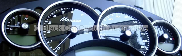
The Mt.Fugi symbols in the Speedo and Tach will not be visible during the day (illumination off)
The Mt.Fugi at the bottom center WILL be visible during the day.
The Symbols in the speedo/tach will light up when the lights are on, and when that happens, the bottom center symbol won't show up (it's unlit)
I'm pretty pumped to get this in hand and continue this project.
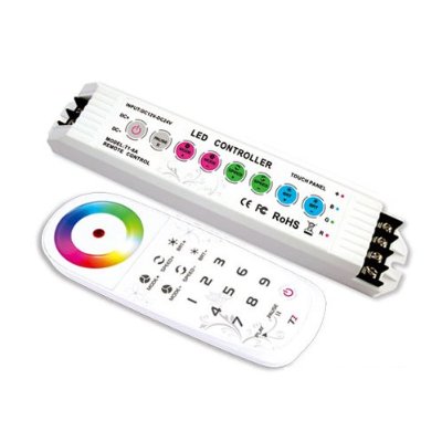
I also got a new controller unit as I was unhappy with the original one. This one Has a rechargable Lithium Ion battery and MUCH better colour control, etc. So the amount of actual colours outputted is broader than it ever was, and so it the control of the colour shift/speed/rate, as well as contrast and hue adjustments. It's recharged via. USB so it's a simple plug in in the car if it ever gets low (Li-Ion not likely to get low more than twice a year lmao)
Also can run 18 AMPS!!! Not that I'll ever use that much, ever, but nice to have the potential.
The Black background will be the High gloss Piano black shown below:
The Mt.Fugi symbols in the Speedo and Tach will not be visible during the day (illumination off)
The Mt.Fugi at the bottom center WILL be visible during the day.
The Symbols in the speedo/tach will light up when the lights are on, and when that happens, the bottom center symbol won't show up (it's unlit)
I'm pretty pumped to get this in hand and continue this project.
I also got a new controller unit as I was unhappy with the original one. This one Has a rechargable Lithium Ion battery and MUCH better colour control, etc. So the amount of actual colours outputted is broader than it ever was, and so it the control of the colour shift/speed/rate, as well as contrast and hue adjustments. It's recharged via. USB so it's a simple plug in in the car if it ever gets low (Li-Ion not likely to get low more than twice a year lmao)
Also can run 18 AMPS!!! Not that I'll ever use that much, ever, but nice to have the potential.
Last edited by TunerMax; Apr 5, 2012 at 08:38 PM.