
Another turbo build


#47
 12-30-2009, 08:53 PM

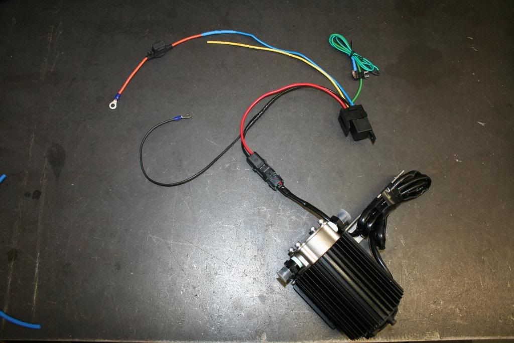
Couple more things that I have not coverd. This is what I really went to school for and where most of my attention to detail originates from. I made the electrical system for the scavenge pumps as simple as possible. Basically all one needs to be able to do is follow the labled wires and pull/plug a fues in:
The relay:
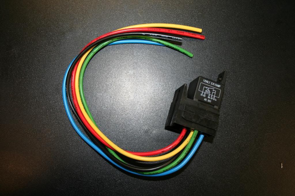
Pin 30 to +12 power (battery)
Pin 85 +V is signal on off (plug to OEM fuse box)
Pin 86 Chassy ground or negative battery terminal
Pin 87 Scavenge pump power
Pin 87a (yellow) spare, I would suggest one runs the power for boost gauge and wideband off of this. This is a good idea because if you loose your lights on the boost gauge/wideband you know that your fuse is blown and scavenge pump is not running. This is how I ran my setup for a year and it works great. Never had blown fuses either, and it is highly unlikely that it will happen.
Water tight connector kit:
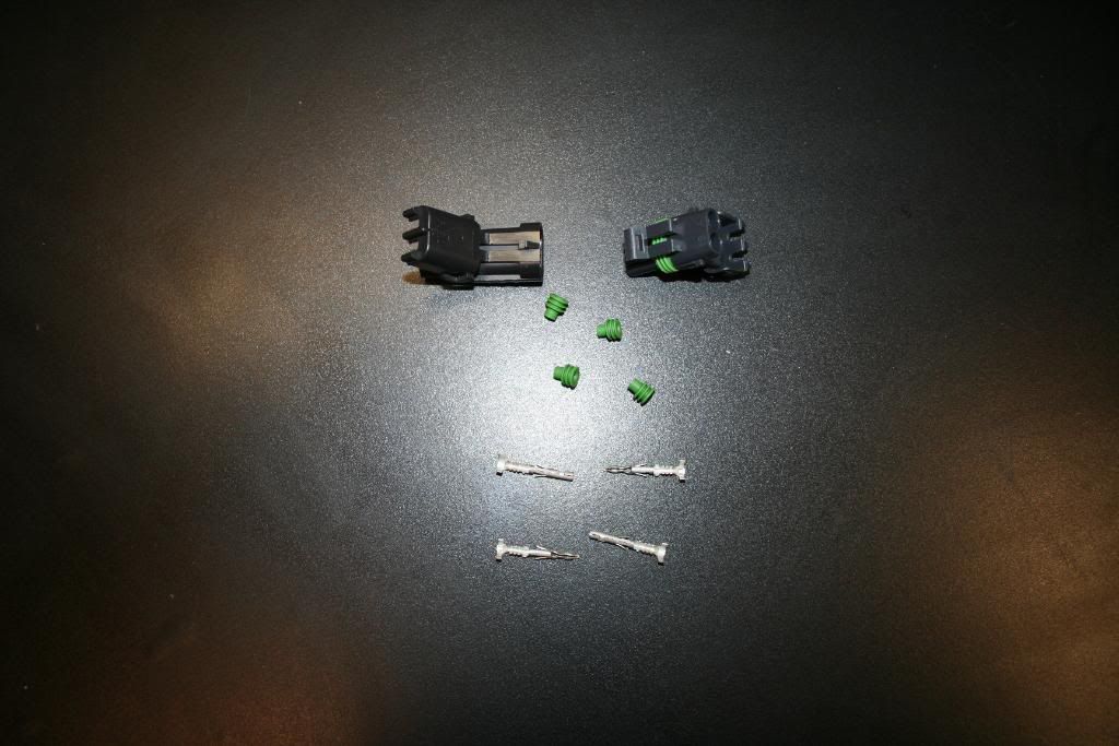
I did not just crimp them on there, I also soldere evrything once crimped. No chance of ever seperating.

Connector done:
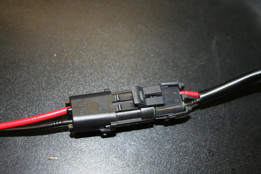
Very important to "tin" the wires before soldering them together. This ensures that the entire wire has been coverd with solder, making it much stronger once soldered to another wire.

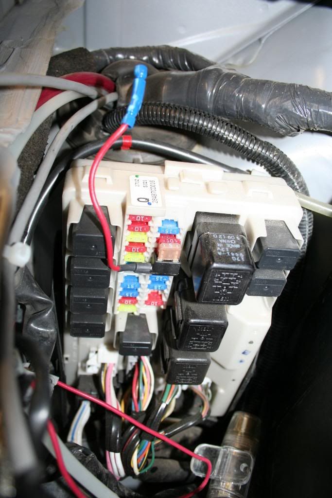
This is my favorite thing. It is an "Add a circuit kit" and allows one to add to the existing OEM circuit without affecting them at all. It simply plugs in to the fuse box and provides you with additional output signal. In this case it is pluge in to the windshield washer circuit. The 10A fuse used to be where the "add a circuit" connector goes, and by pluging it in where it is, it remains as a part of the OEM circuit. The 5A fuse is for the new relay on/off signal.
Tested and working, this is how it will be setup/premade ready to go. Like mentioned above, the yellow wire is an additional +12v circuit and I would suggest running the boost gauge/wideband off of it. Very much a plug and play setup:
The relay:
Pin 30 to +12 power (battery)
Pin 85 +V is signal on off (plug to OEM fuse box)
Pin 86 Chassy ground or negative battery terminal
Pin 87 Scavenge pump power
Pin 87a (yellow) spare, I would suggest one runs the power for boost gauge and wideband off of this. This is a good idea because if you loose your lights on the boost gauge/wideband you know that your fuse is blown and scavenge pump is not running. This is how I ran my setup for a year and it works great. Never had blown fuses either, and it is highly unlikely that it will happen.
Water tight connector kit:
I did not just crimp them on there, I also soldere evrything once crimped. No chance of ever seperating.
Connector done:
Very important to "tin" the wires before soldering them together. This ensures that the entire wire has been coverd with solder, making it much stronger once soldered to another wire.
This is my favorite thing. It is an "Add a circuit kit" and allows one to add to the existing OEM circuit without affecting them at all. It simply plugs in to the fuse box and provides you with additional output signal. In this case it is pluge in to the windshield washer circuit. The 10A fuse used to be where the "add a circuit" connector goes, and by pluging it in where it is, it remains as a part of the OEM circuit. The 5A fuse is for the new relay on/off signal.
Tested and working, this is how it will be setup/premade ready to go. Like mentioned above, the yellow wire is an additional +12v circuit and I would suggest running the boost gauge/wideband off of it. Very much a plug and play setup:
#48
01-01-2010, 10:30 PM


#49
01-02-2010, 01:02 AM
I ordered 12 sets from the US. They also sell them at Mopac, but they are significantly more expensive.
#50
01-17-2010, 09:49 PM
Some good news, starting tomorrow, I will be a vendor on my350z.com. Right now I am trying to get 3 more kits done, and stock up on "spare" part. I will have at least one of everything handy so if something does go with a customer’s kit, I can just ship the new part out.
I will have a G35 in my garage for a week starting next weekend, so this will give me a chance to test fit everything on a G. I am certain that the kit will just bolt right up, as it does on the Z. The only thing that may be different is the way the charge air gets routed from the IC to the TB, but that is no big deal.
I will have a G35 in my garage for a week starting next weekend, so this will give me a chance to test fit everything on a G. I am certain that the kit will just bolt right up, as it does on the Z. The only thing that may be different is the way the charge air gets routed from the IC to the TB, but that is no big deal.
#52
01-18-2010, 12:31 AM

Also in to know if Karma got some gonads and is going force induction.
#53
01-18-2010, 12:31 AM
AidanP is the user name on here. I think Sean (Karma) is scared..
I will take a bunch of pictures for you guys, so that you can check it out for yourself. Or if any one of you wants to swing by and check it out in person, you are more than welcme too.
I will take a bunch of pictures for you guys, so that you can check it out for yourself. Or if any one of you wants to swing by and check it out in person, you are more than welcme too.
#54
01-18-2010, 12:33 AM
1 in 2 out intercooler, so all I need is a car.

#56
01-18-2010, 12:59 AM


#57
01-18-2010, 01:12 AM

#60
01-21-2010, 04:56 PM