
Semi DIY: 03-05 Dual ring taillights


Semi DIY: 03-05 Dual ring taillights
I would like to thank Albert (E_K) for his great help. His answers to my questions were very helpful. Definitely made this job MUCH easier.
I suck at write-ups, not sure how many of you will find this helpful but what the heck lol. so THIS IS NOT A FULLY DETAILED WRITEUP, This should give you a very close idea on how to do it. Common sense is definitely needed.
This might seem like a complicated job, but it was pretty simple and fun to do. It all comes down to how good you are with your hands.
PLEASE do the cutting outside. When cutting with the Dremel plastic pieces WILL FLY all over the place. so please make sure to wear safety glasses. Also rotary cutting tools spin pretty quick and can slip easily. Practice on something before you start cutting into the lights & skin.
I took many pics when I did my dual ring taillights. I will post the pictures now and edit it later when I get a chance.
What you need is:
07+ G35 Sedan taillights
03-05 G35 coupe tail lights. (06+ might work, however cutting around the trunk button might be a PITA)
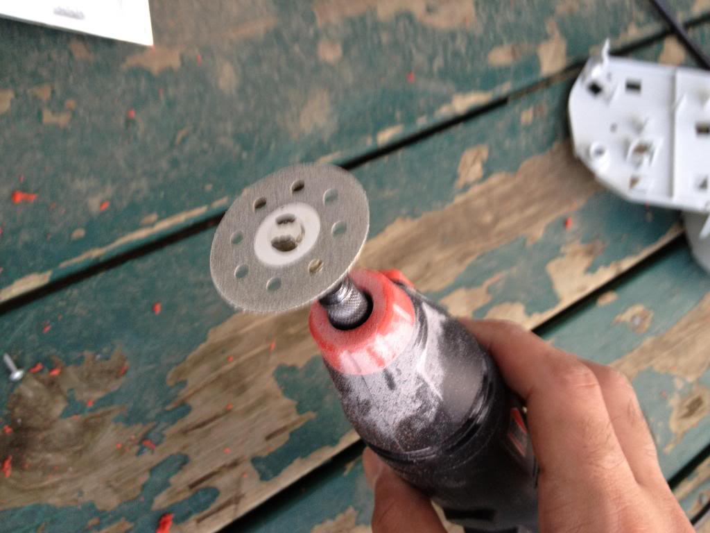
Dremel with diamond cutting bit. (will post pics)
Safety glasses is a MUST
Glue/sealant. (Will post pics)
Forgot to take pics on cutting the G35 sedan tail lights.
If you cant do that without this thread, you really should not proceed with this
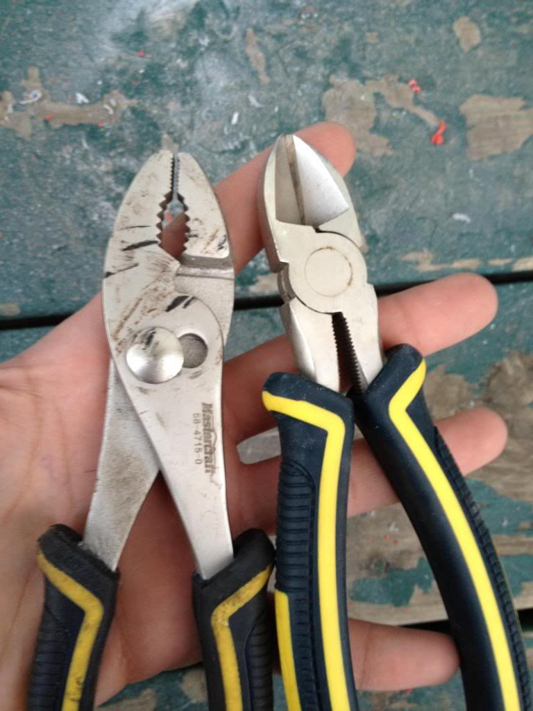
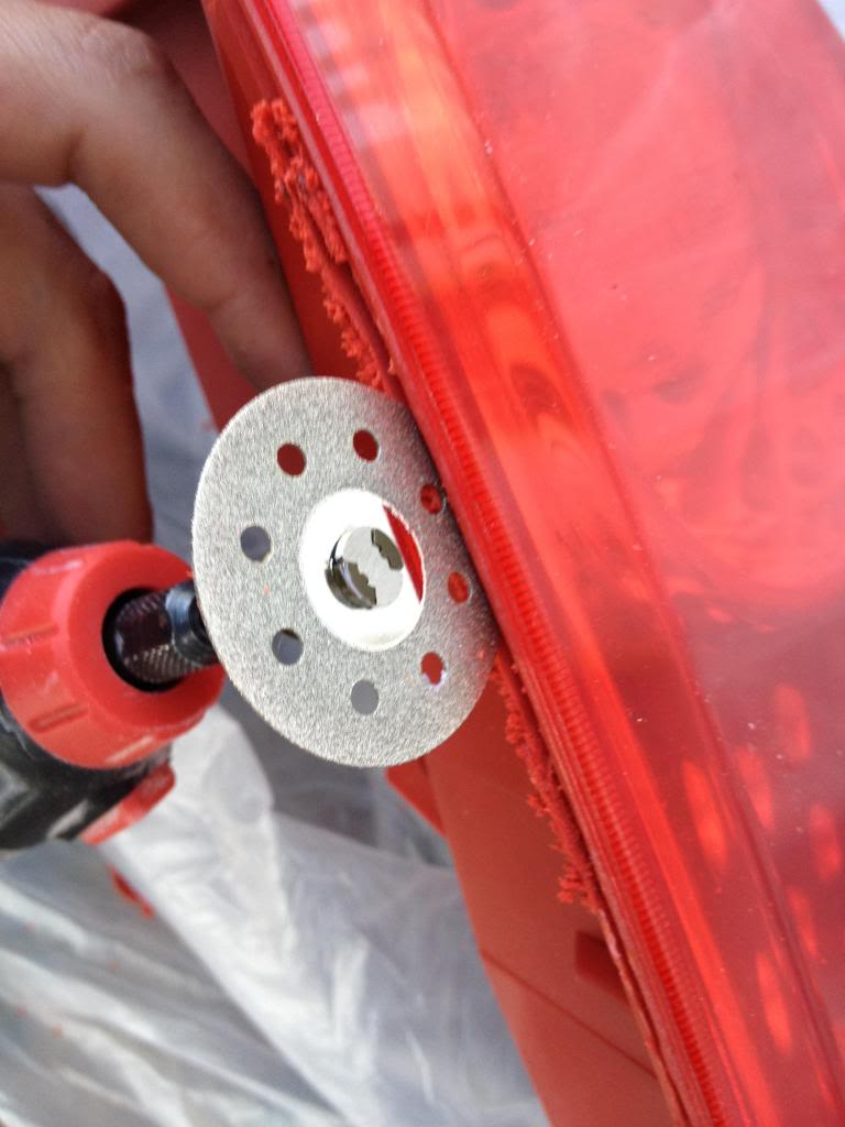
Cutting tool:
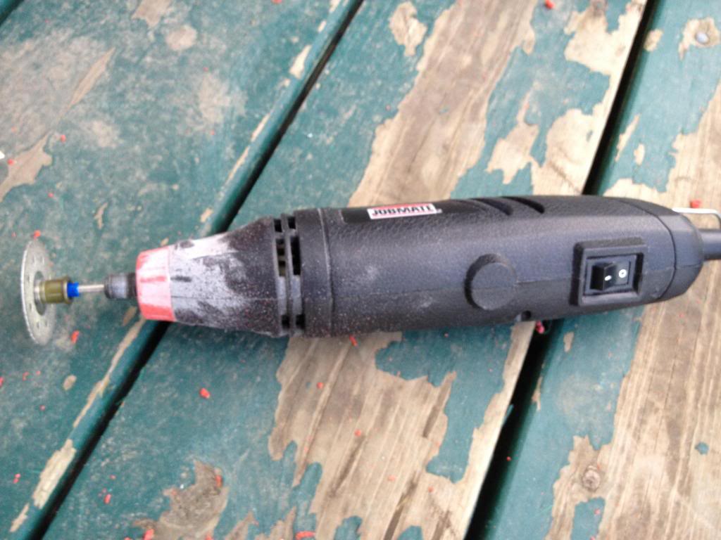
Cutting Bit. (diamond cutting bit). The thinner the better.
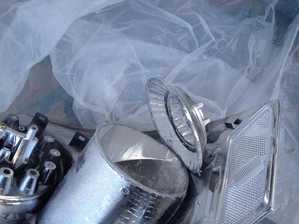
After cutting into the sedan tails
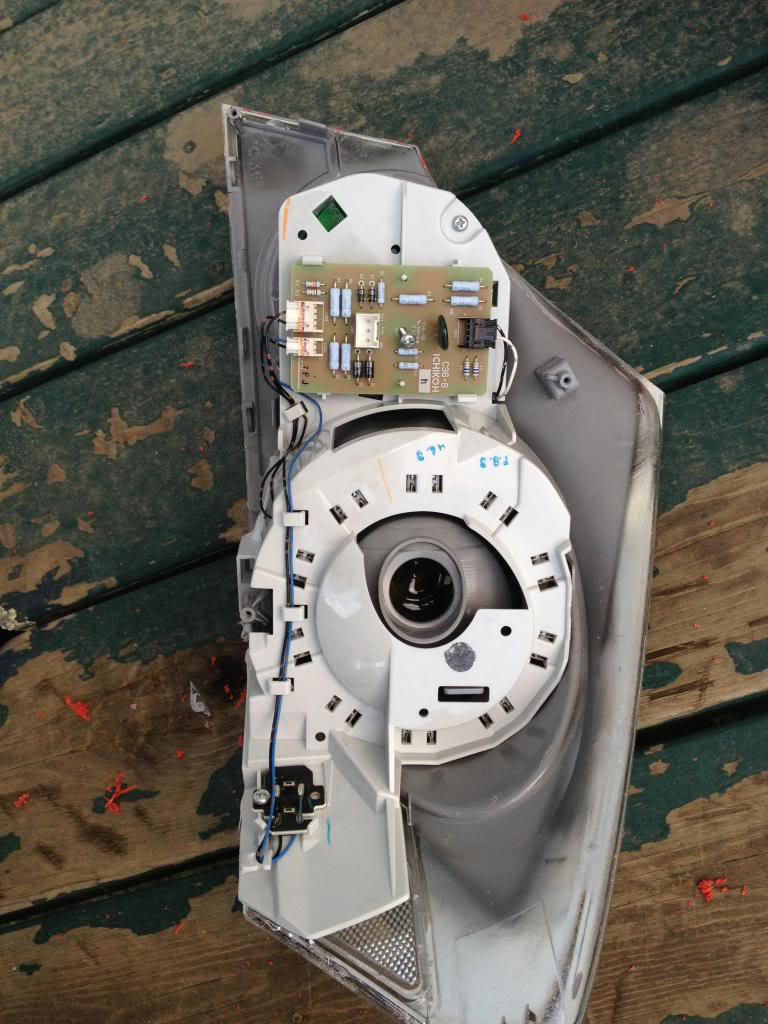
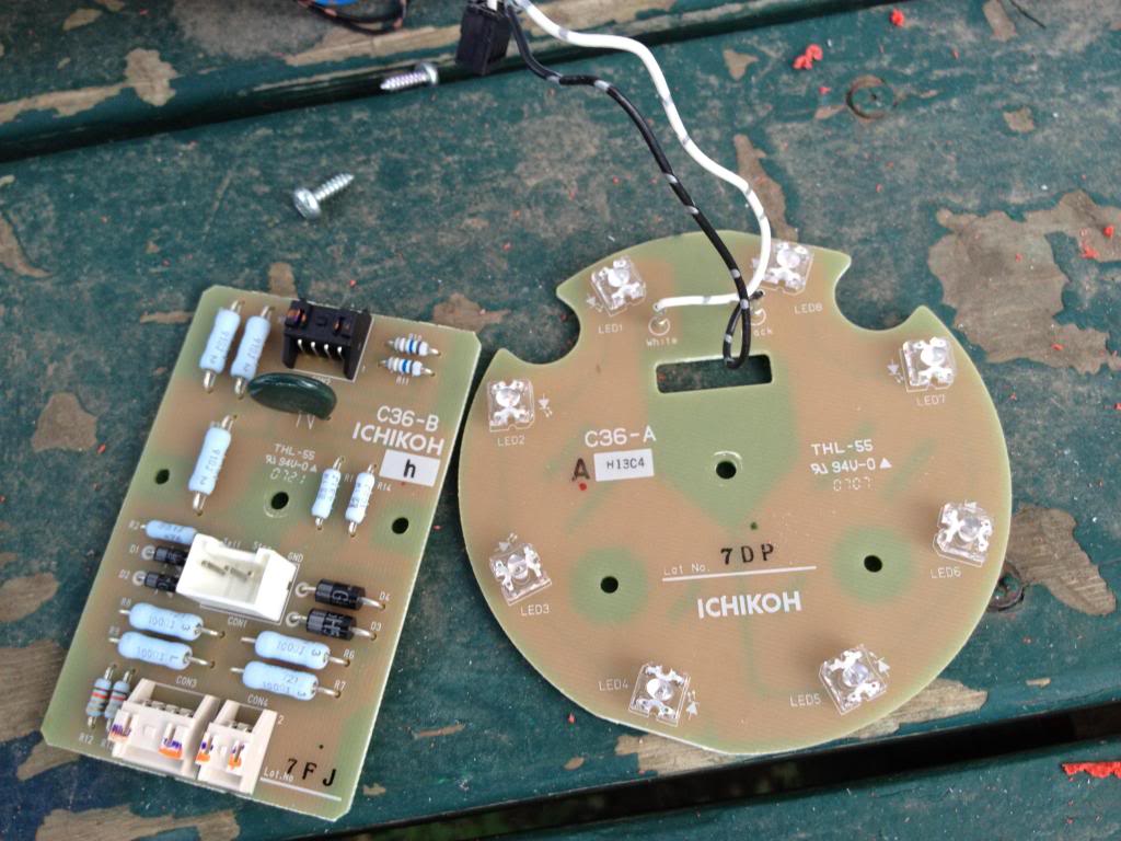
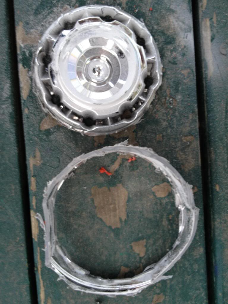
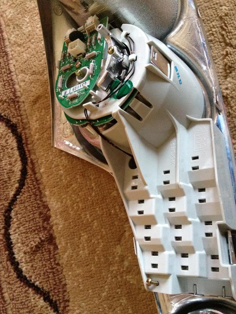
separate the LEDs from the housing
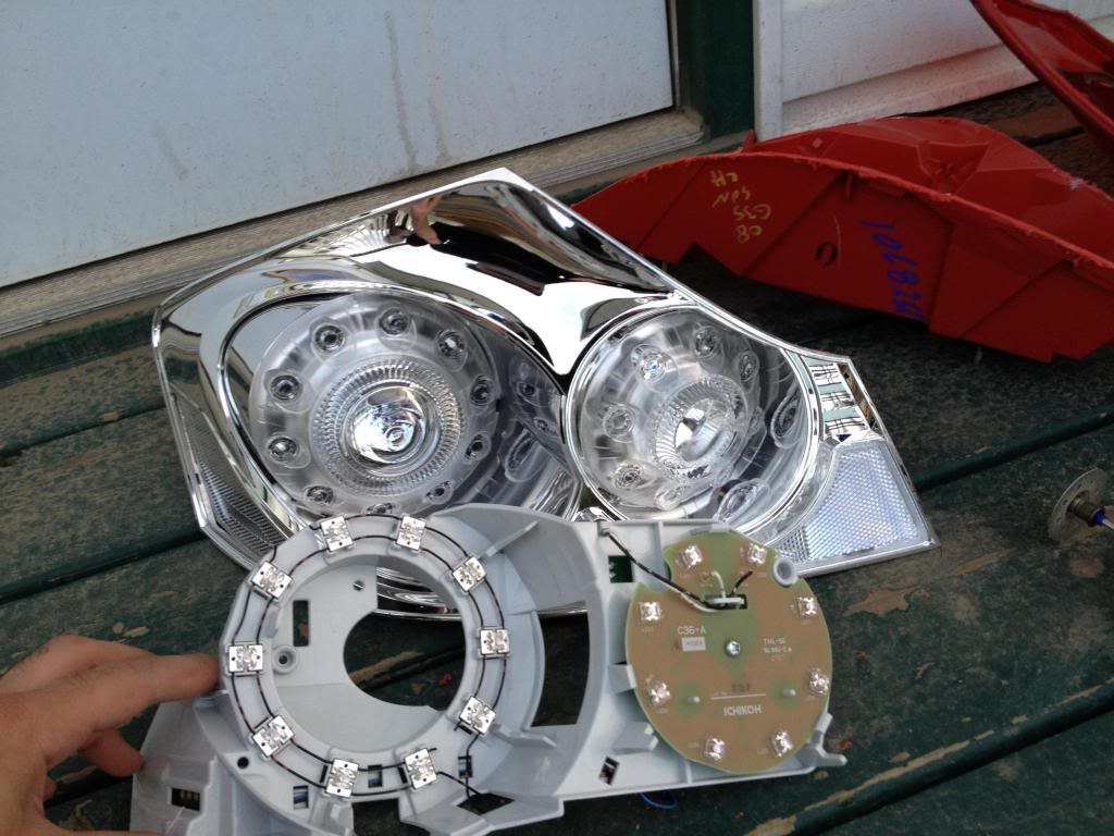
unscrew the LED & circuit and put it aside.
Now you need to remove the ring where the LEDs sit. This is where you need a steady hand. Take your time, measure twice cut once. I did this very carefully and as 4 different stages
cut the main piece out
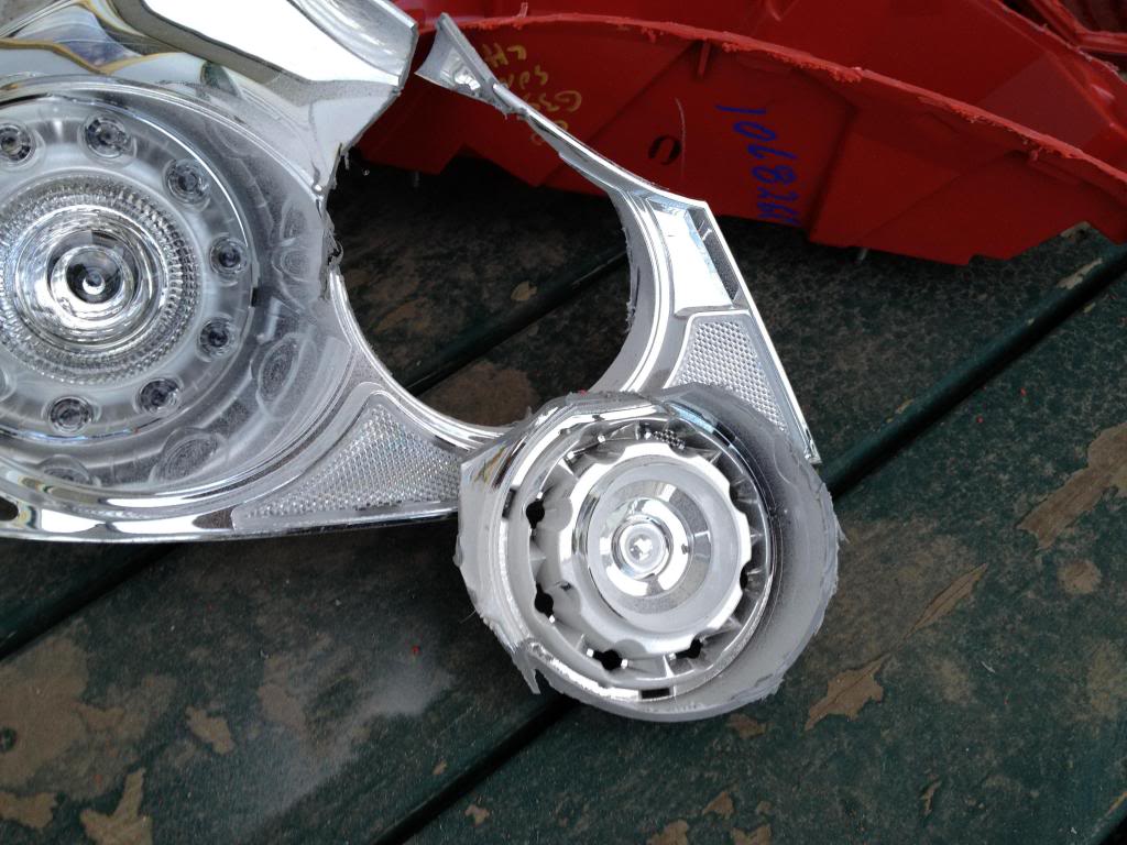
trim it more
and more (I started making small cuts and prying them off with players/cutters
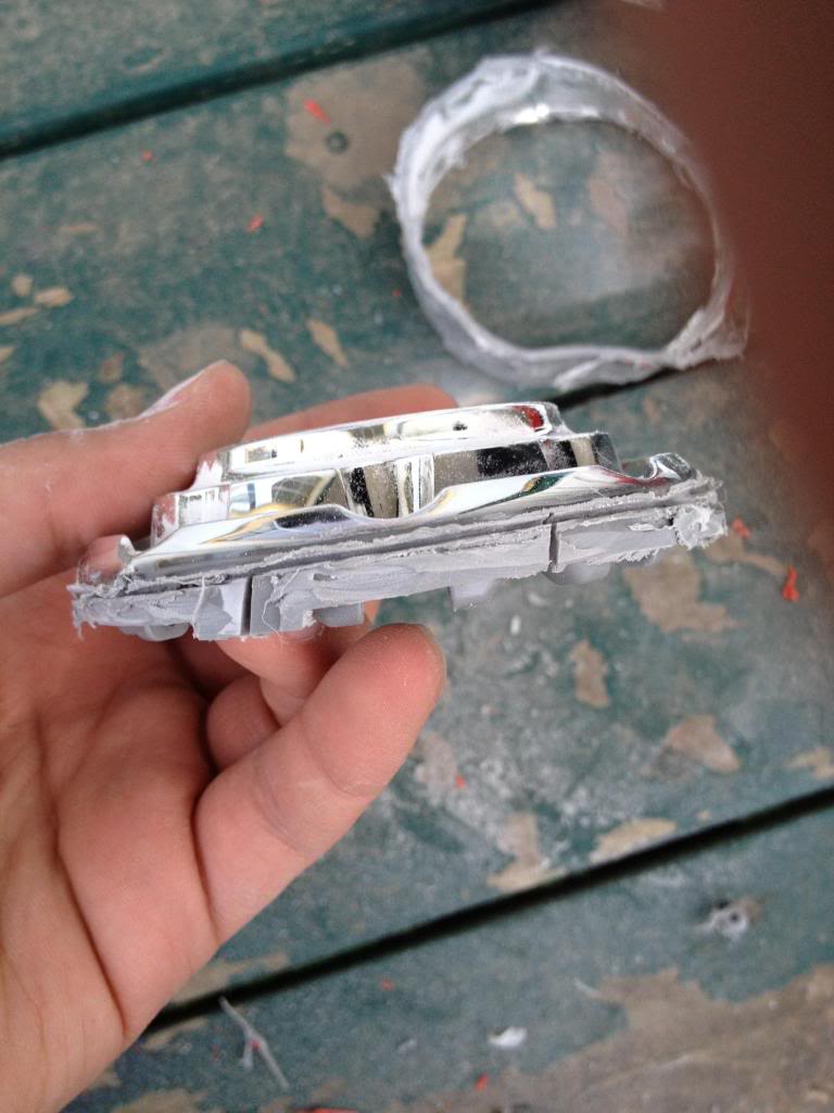

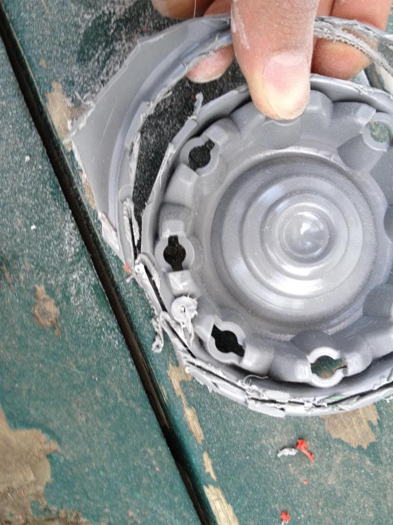
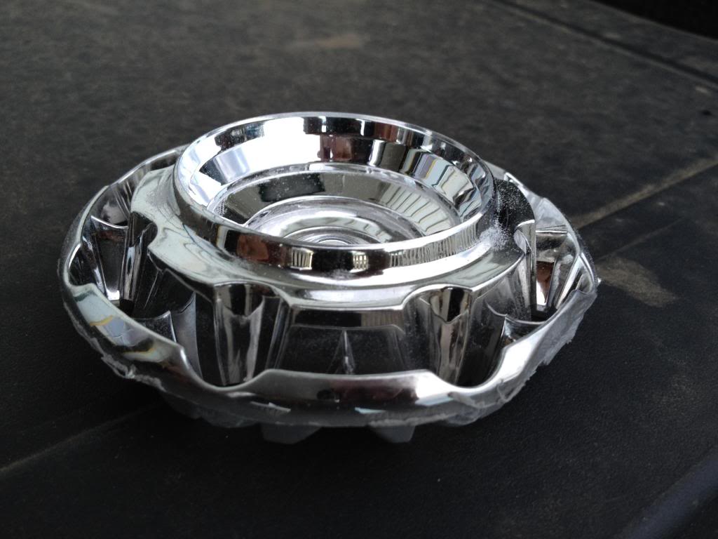
you should end up with something like this
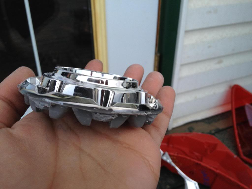
sanding down the edge to get it smooth helps, but not a must.
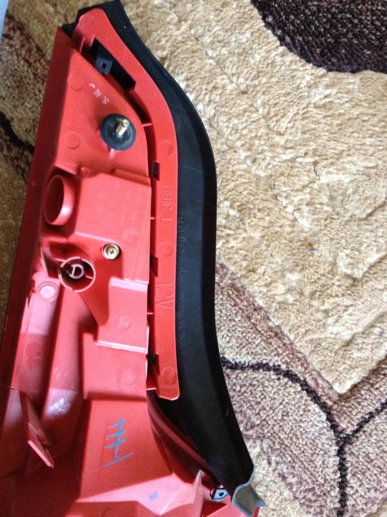
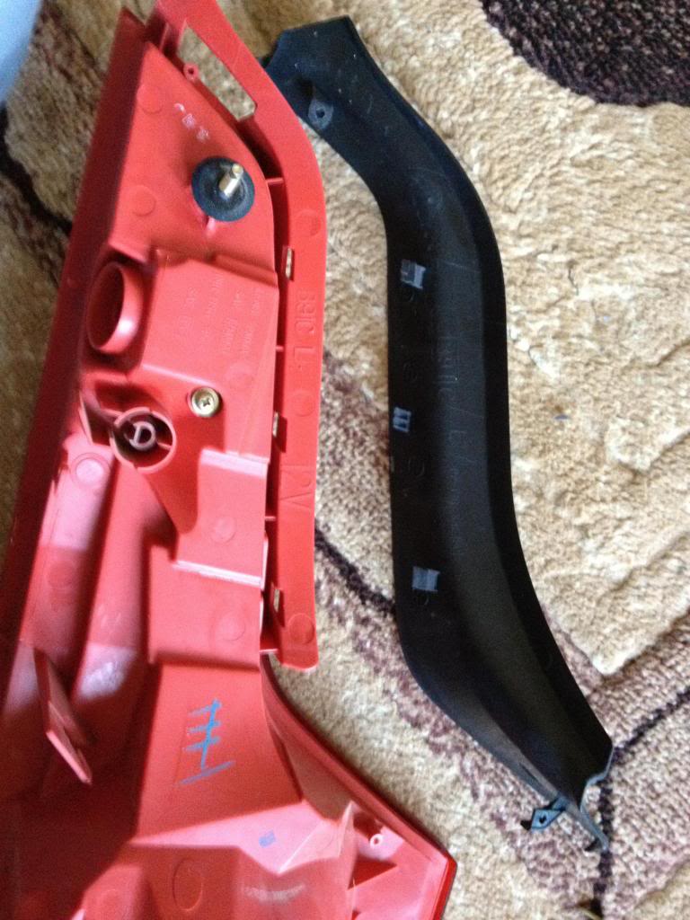
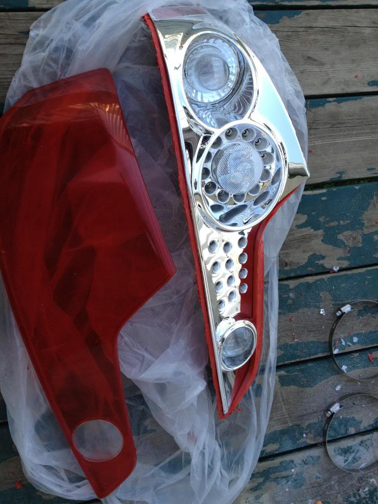
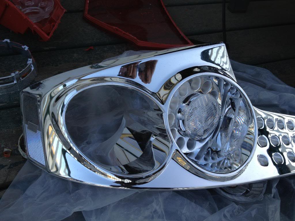
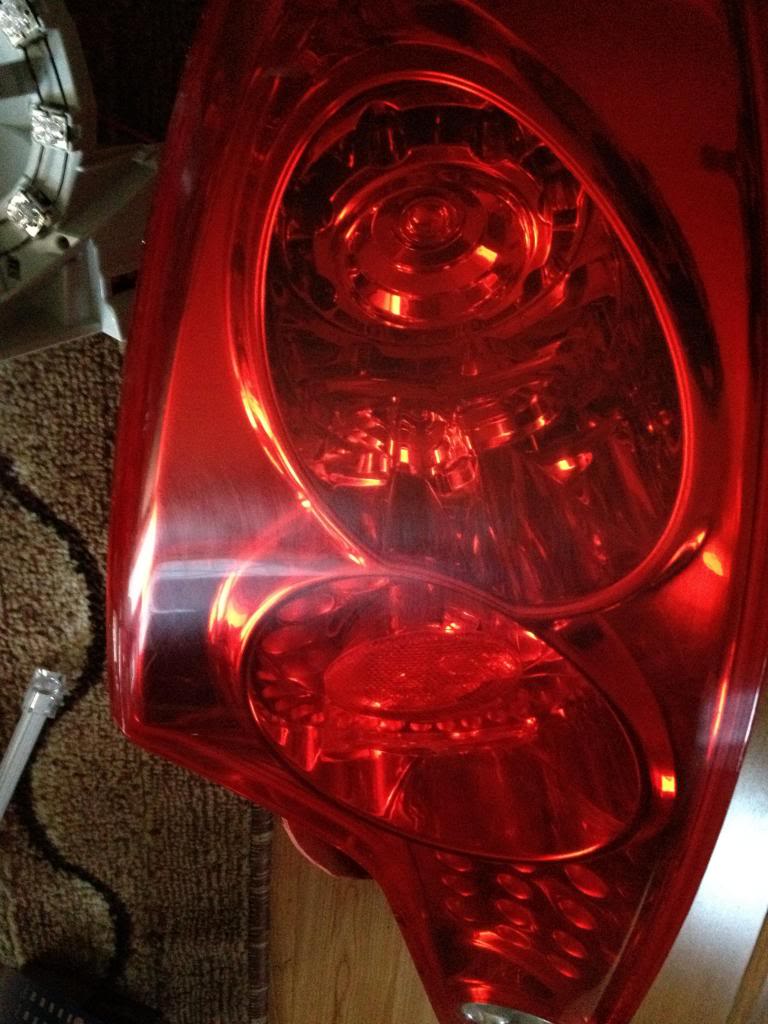
Now to the Coupe tail light.
Remove the black piece, I believe its held by two screws and 3 clips?
Point of NO return
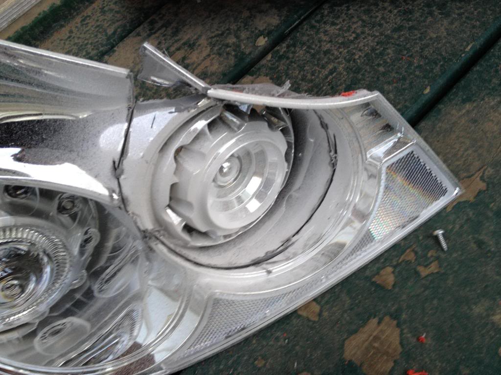
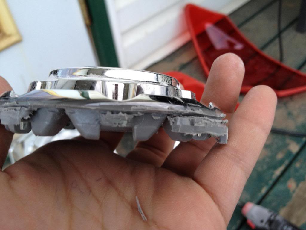
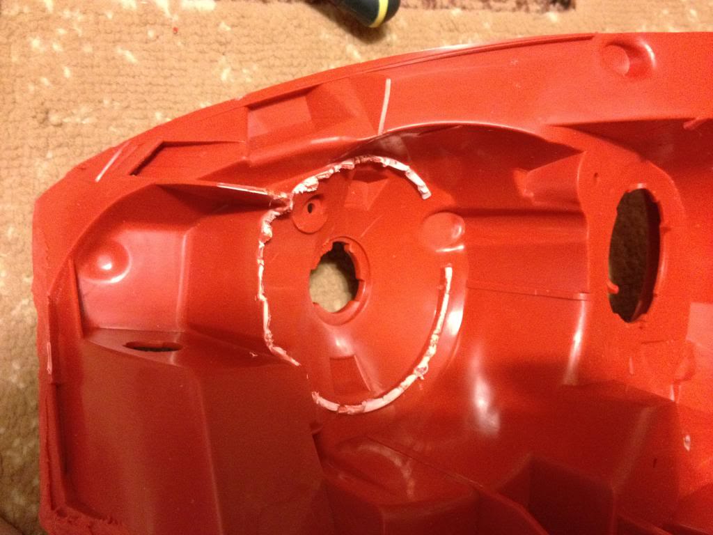
Start cutting around the edge. DO NOT and i repeat DO NOT put the dremel disk all the way in. Doing so will cut through the chrome of the coupe tail light even the outside of the housing (red lens), cut the surface only and start going deeper until you see its cut through.
Like this
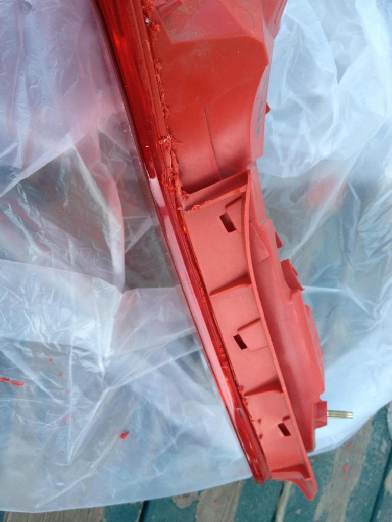
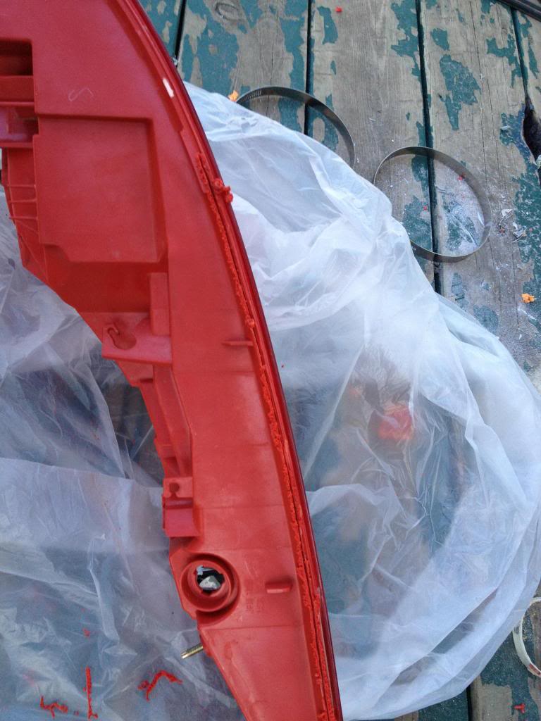
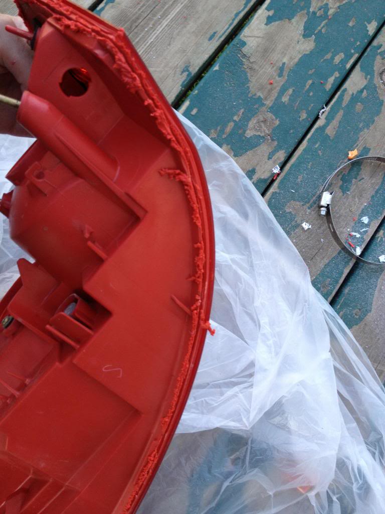
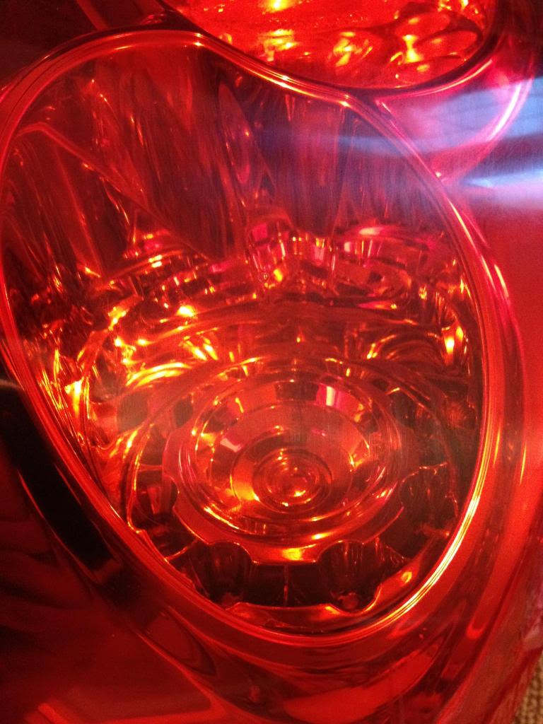
Once you cut it all, open the housing, since the plastic melts while cutting, it might stay together as one piece after cutting. Look all around the edge and see where it still needs cutting.
The chrome housing is held by clips only. so work your way around it to get it out. don't use too much force, or you will crack it.
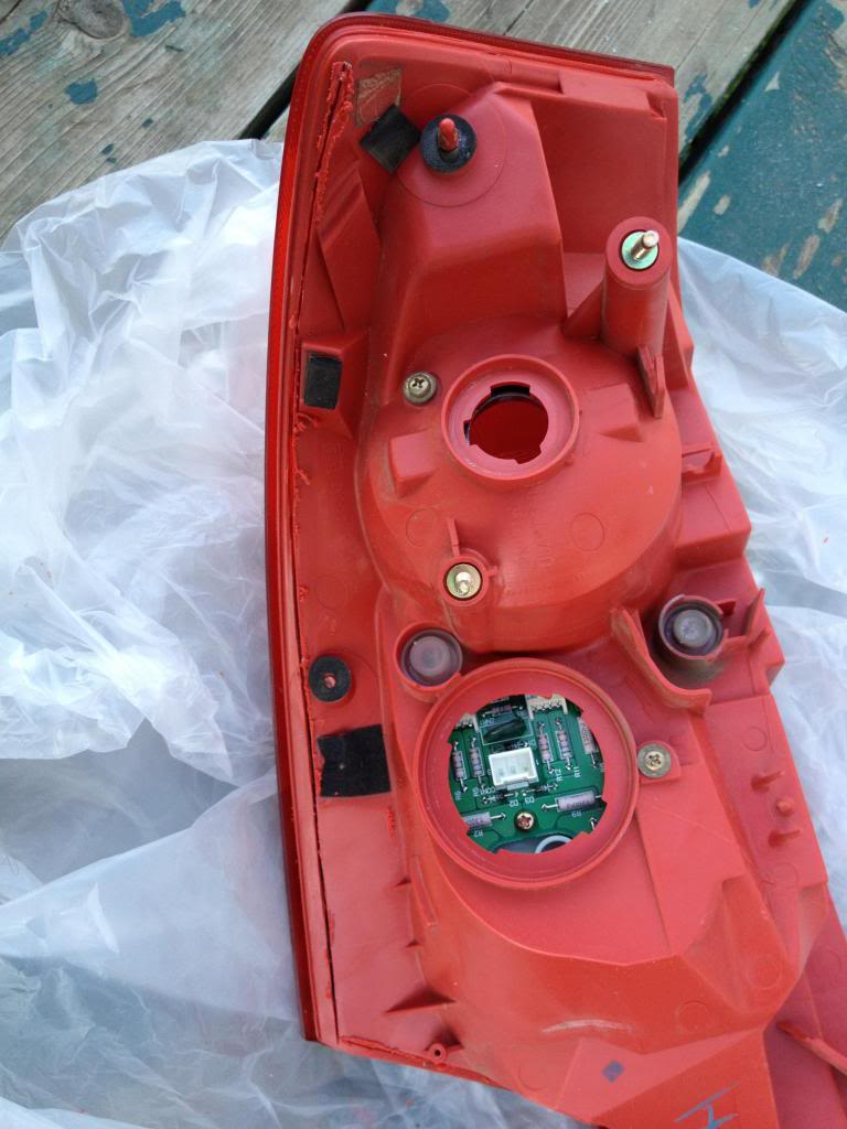
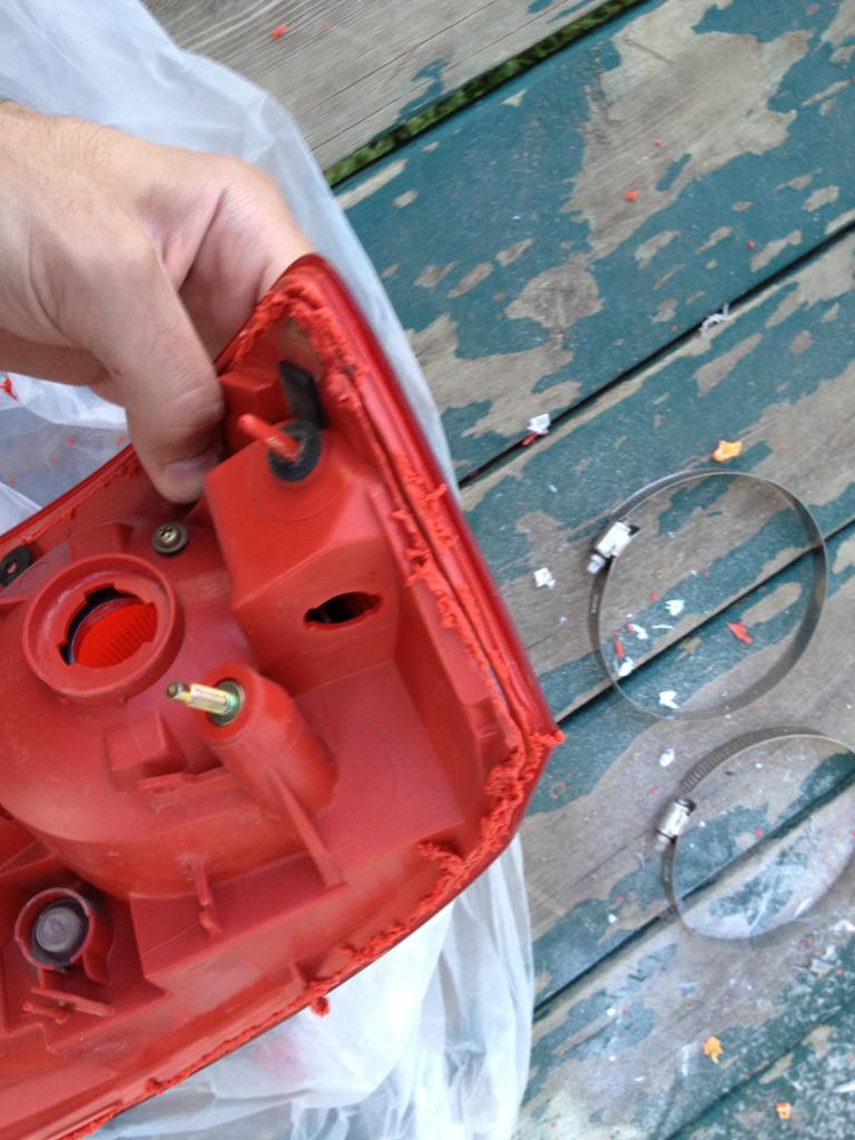
Remove the LEDs, They are held by two screws I think. and a tab.
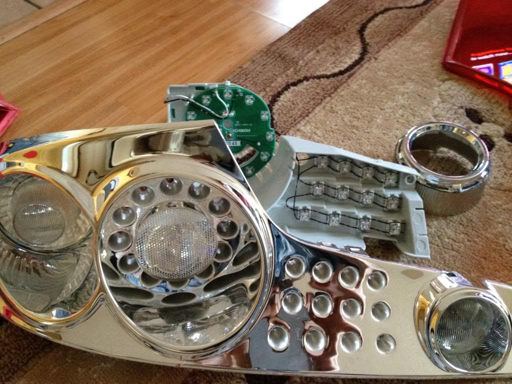
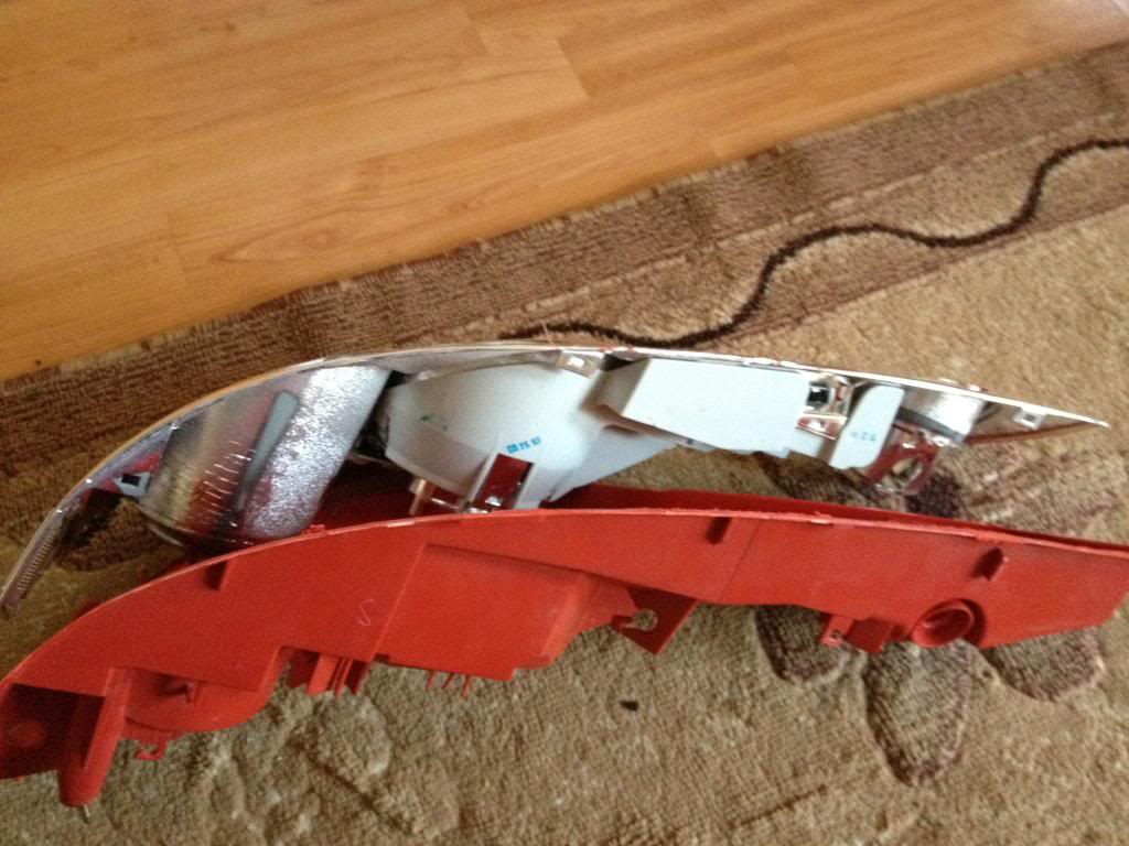
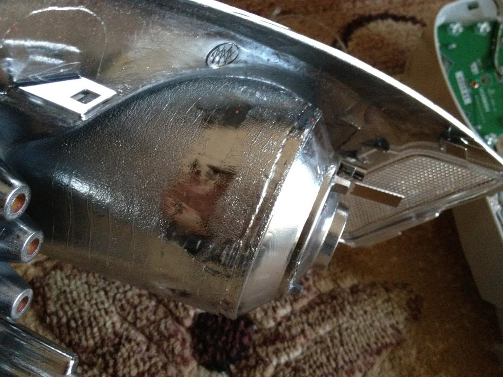
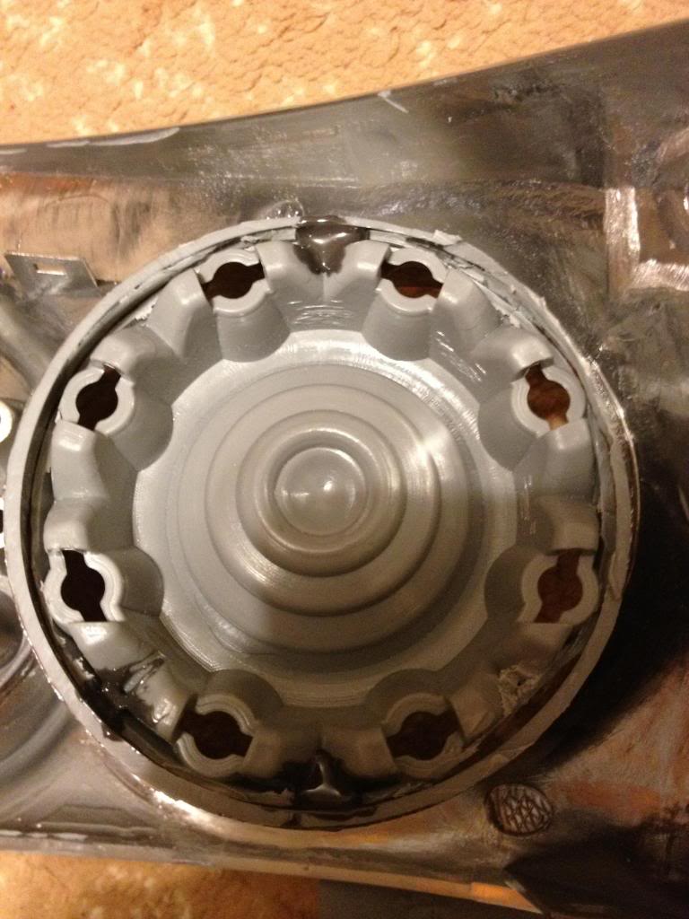
Now gotta make room for the new ring, so gotta remove the turn signal housing portion of the tail lights
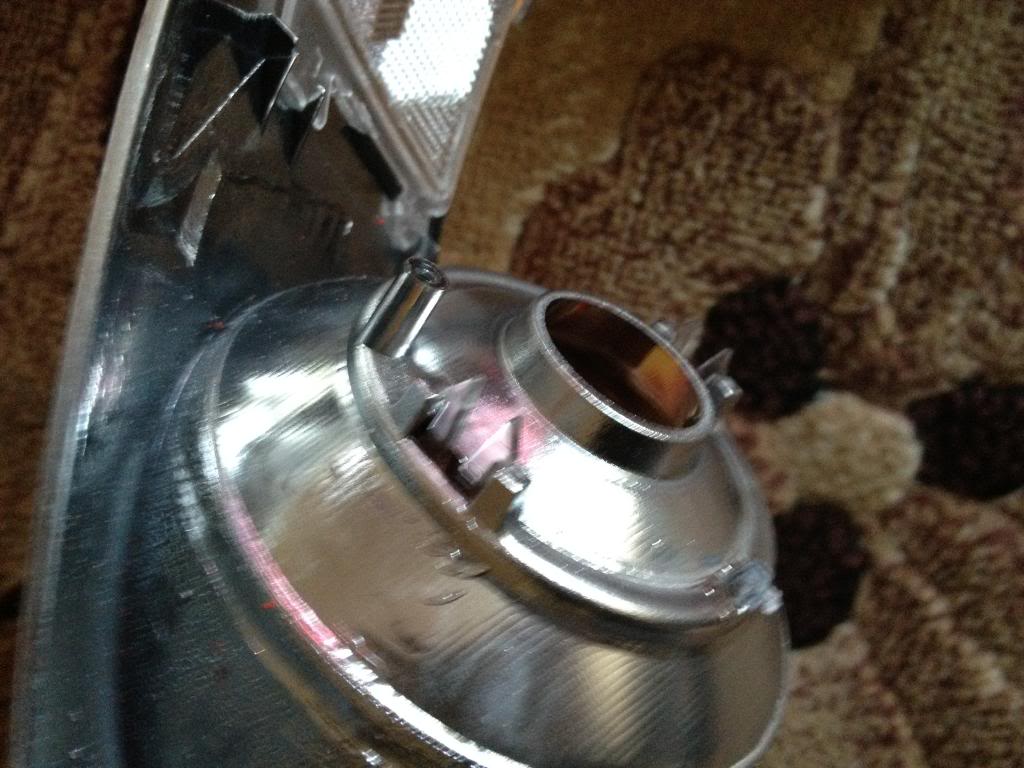
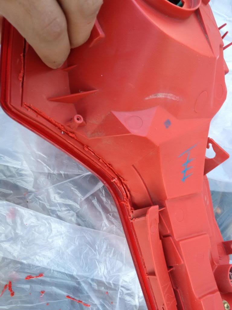
With that piece being out, the ring should fit there. If its too tight and not sitting flush with the back then you need to do some more trimming. Cut only a little at a time
Its important for the ring to be flush with the back, otherwise the LED ring will not sit properly
Once you see that its sitting flush with the back and straight in the front, apply some glue to the circle so it doesnt move out anymore.
Make sure the glue doesnt leak to the front.
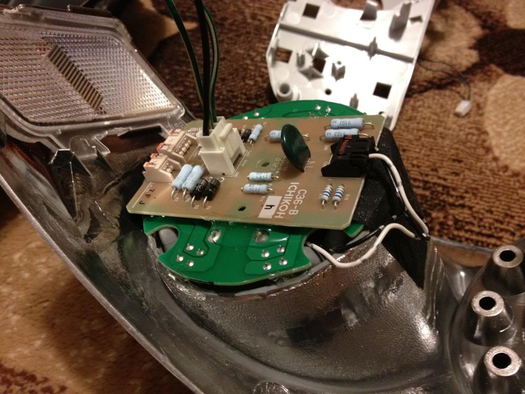
once dry, take the LED ring and put it there, it should sit there just right. Use some tape to hold it and then apply glue on the side to hold the ring in place.
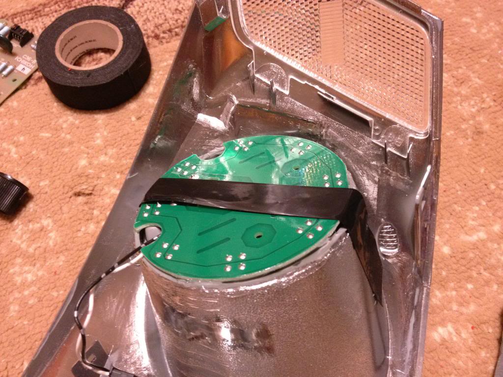
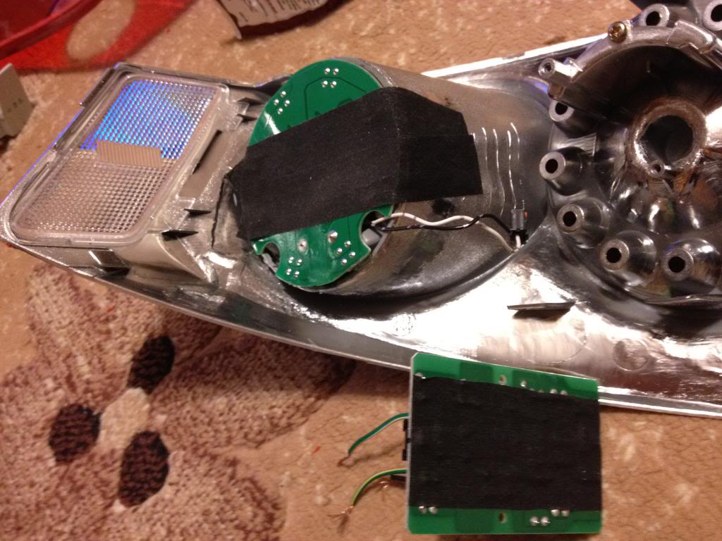
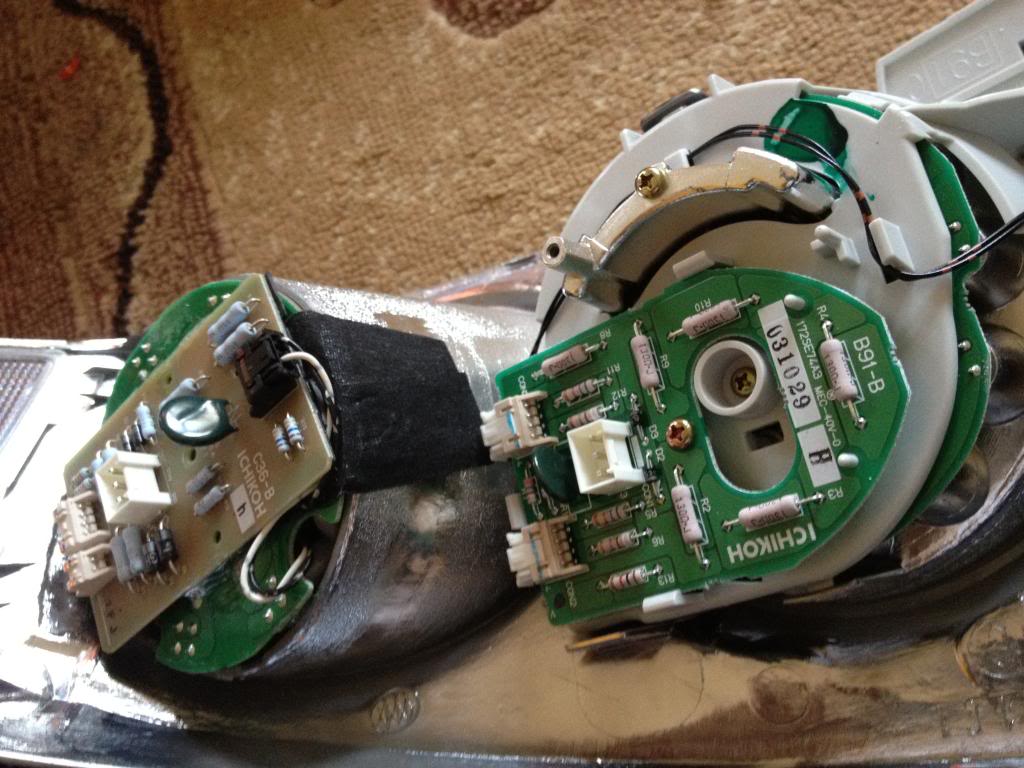
Use TWO layers of double sided tape on the back of the led to set the circuit board. If you dont use two you might get the connectors to short and some of the LEDs might not work. Happened to me, It was a PITA to do this all over again.
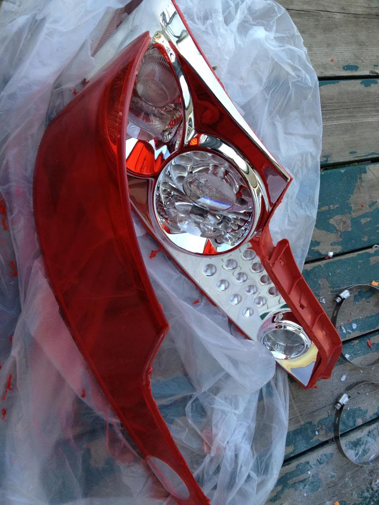
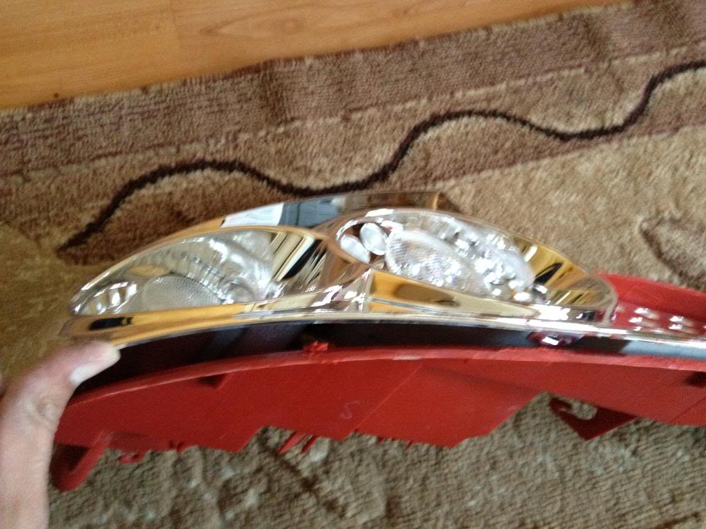
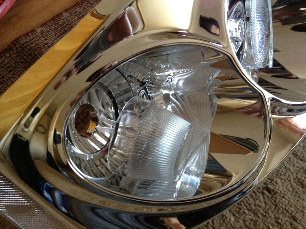
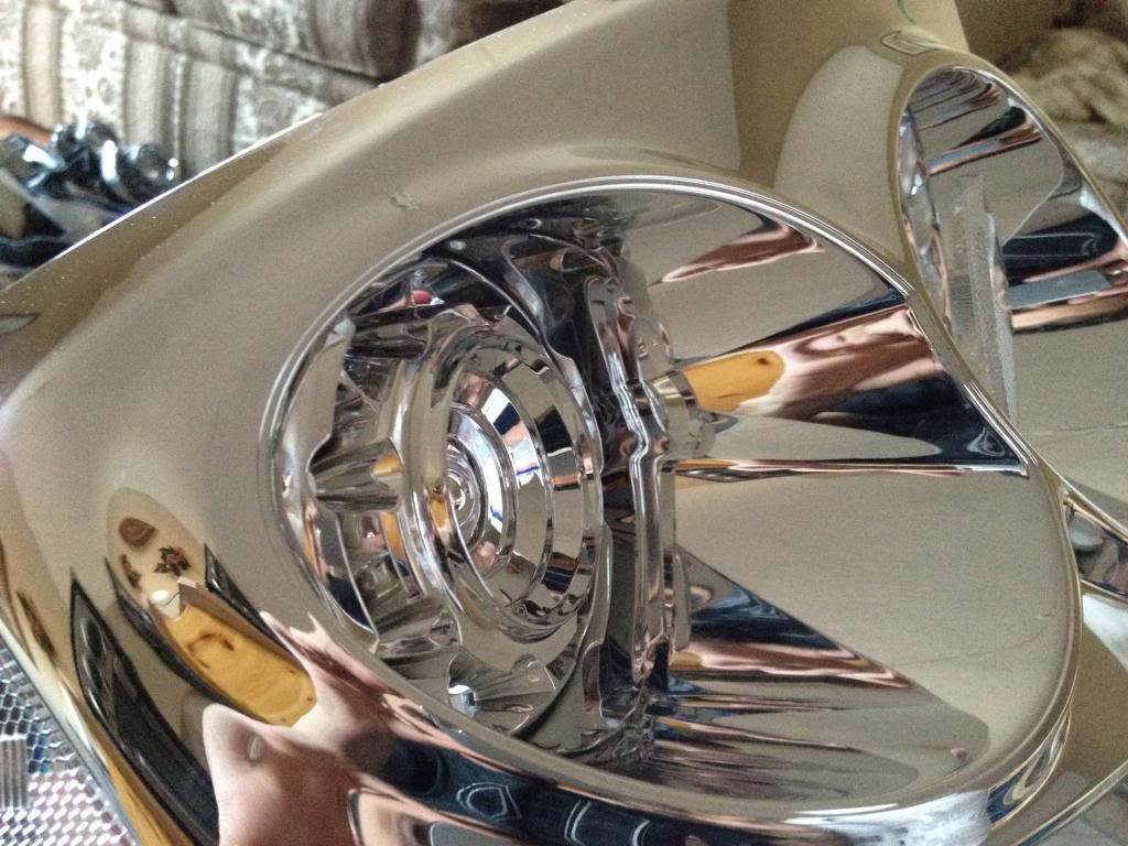
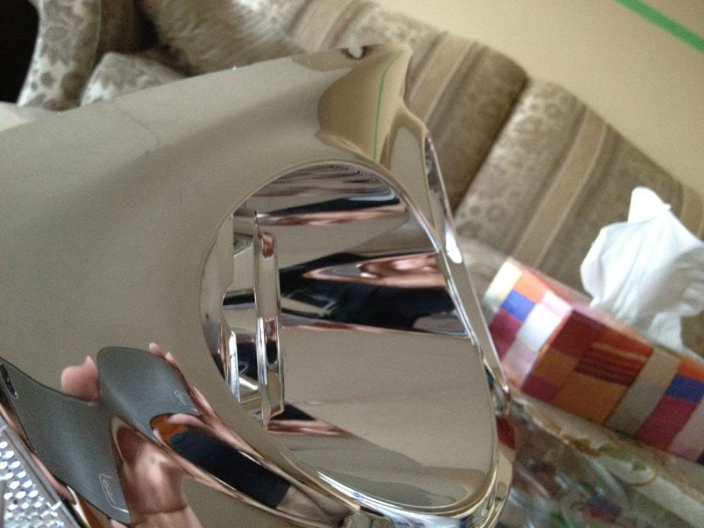
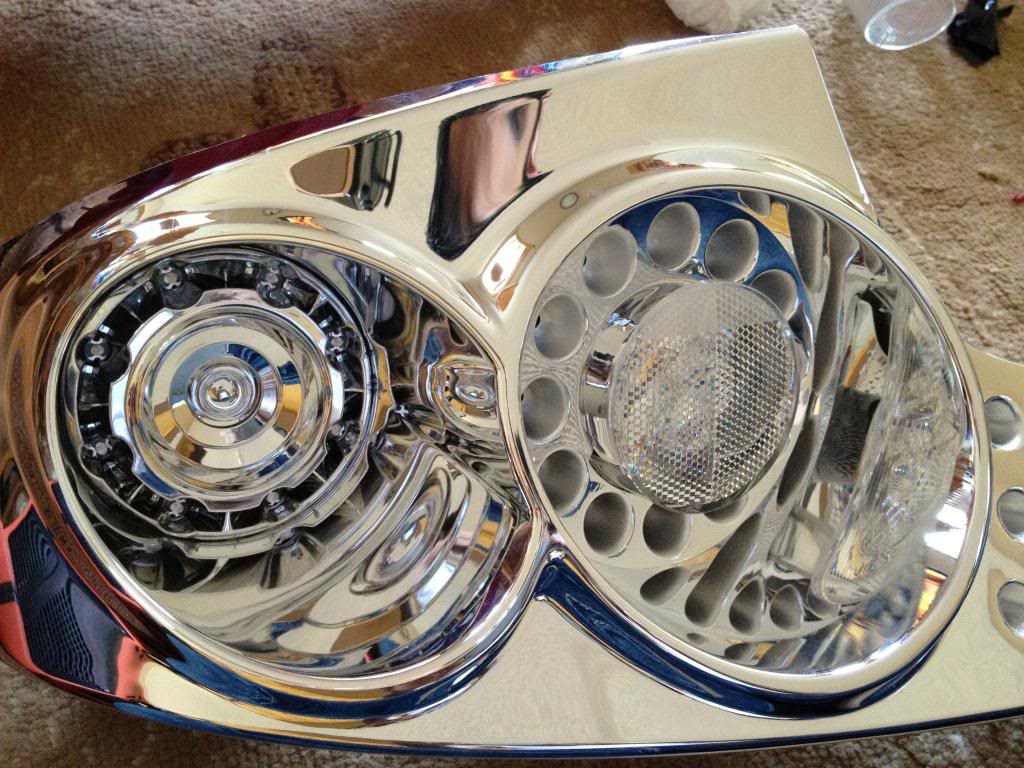
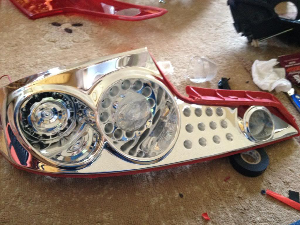
font view
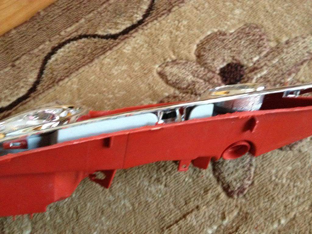
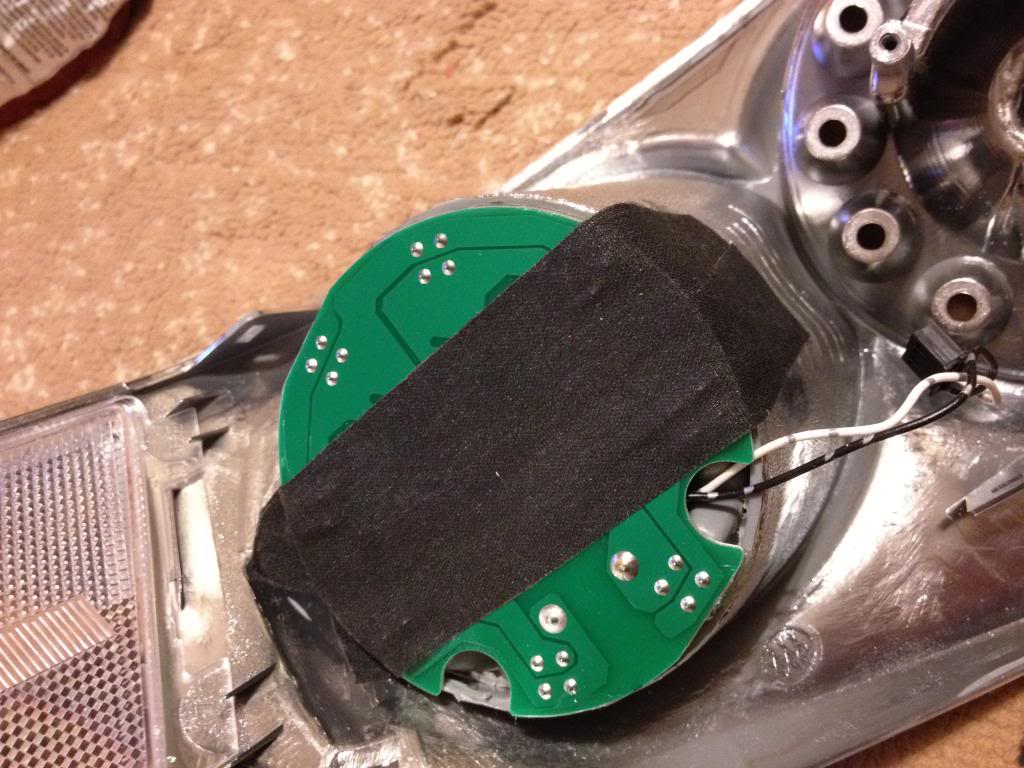
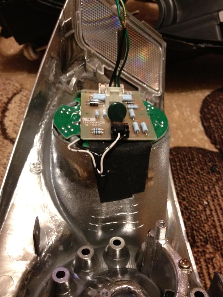
now trim the back of the housing like this, otherwise the connector on the board will not clear
start putting everything back together
Put the lens back on the backing. make sure its aligned straight and then use glue to secure it and seal it. I used Goop glue & sealant. Used it many times before i head & tail lights and never ever had an issue with condensation.
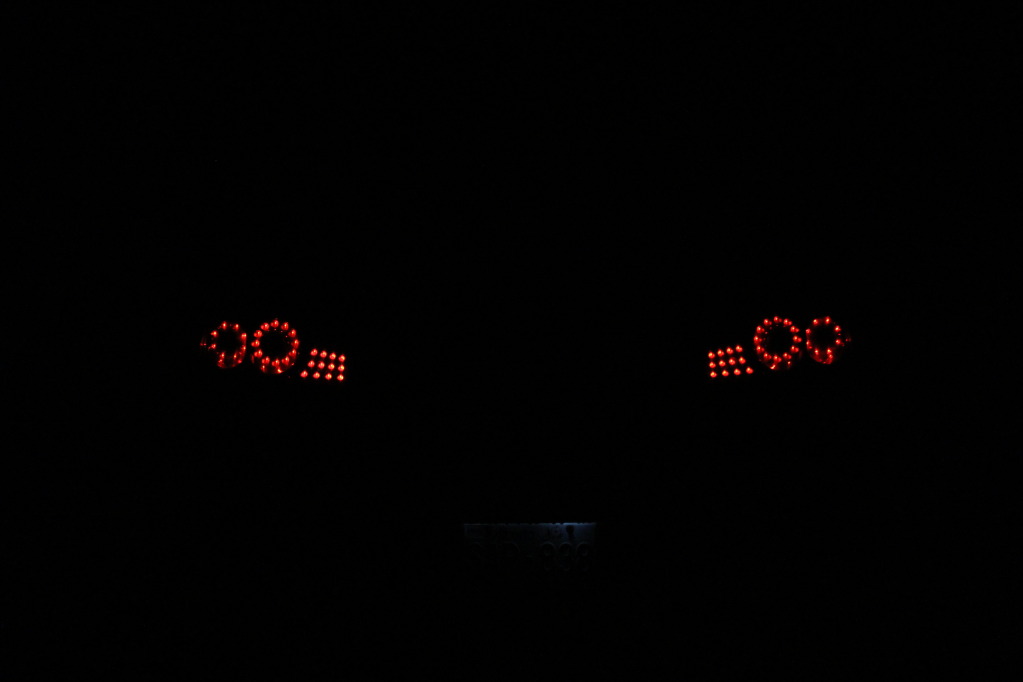
Now you need to decide on how you want to light up. I have it dimmed with running lights bright with signal on. So when brakes applied the second circle stay dimmed.
In this video I was testing the LEDs. What you will see is taillights when lights are on, followed by brakes on then off. turn signal on then off. brakes on with turning signal on.
http://s953.photobucket.com/albums/a...t=IMG_2802.mp4
Comparing both
****Adding dual LED ring will cause your signal to hyper blink, so you will need a load equalizer on each side. they are like 15 bucks a pair shipped****
I'm tired as ****, I'll get to the wiring tomorrow
I suck at write-ups, not sure how many of you will find this helpful but what the heck lol. so THIS IS NOT A FULLY DETAILED WRITEUP, This should give you a very close idea on how to do it. Common sense is definitely needed.
This might seem like a complicated job, but it was pretty simple and fun to do. It all comes down to how good you are with your hands.
PLEASE do the cutting outside. When cutting with the Dremel plastic pieces WILL FLY all over the place. so please make sure to wear safety glasses. Also rotary cutting tools spin pretty quick and can slip easily. Practice on something before you start cutting into the lights & skin.
I took many pics when I did my dual ring taillights. I will post the pictures now and edit it later when I get a chance.
What you need is:
07+ G35 Sedan taillights
03-05 G35 coupe tail lights. (06+ might work, however cutting around the trunk button might be a PITA)
Dremel with diamond cutting bit. (will post pics)
Safety glasses is a MUST
Glue/sealant. (Will post pics)
Forgot to take pics on cutting the G35 sedan tail lights.
If you cant do that without this thread, you really should not proceed with this
Cutting tool:
Cutting Bit. (diamond cutting bit). The thinner the better.
After cutting into the sedan tails
separate the LEDs from the housing
unscrew the LED & circuit and put it aside.
Now you need to remove the ring where the LEDs sit. This is where you need a steady hand. Take your time, measure twice cut once. I did this very carefully and as 4 different stages
cut the main piece out
trim it more
and more (I started making small cuts and prying them off with players/cutters
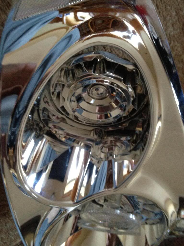
you should end up with something like this
sanding down the edge to get it smooth helps, but not a must.
Now to the Coupe tail light.
Remove the black piece, I believe its held by two screws and 3 clips?
Point of NO return
Start cutting around the edge. DO NOT and i repeat DO NOT put the dremel disk all the way in. Doing so will cut through the chrome of the coupe tail light even the outside of the housing (red lens), cut the surface only and start going deeper until you see its cut through.
Like this
Once you cut it all, open the housing, since the plastic melts while cutting, it might stay together as one piece after cutting. Look all around the edge and see where it still needs cutting.
The chrome housing is held by clips only. so work your way around it to get it out. don't use too much force, or you will crack it.
Remove the LEDs, They are held by two screws I think. and a tab.
Now gotta make room for the new ring, so gotta remove the turn signal housing portion of the tail lights
With that piece being out, the ring should fit there. If its too tight and not sitting flush with the back then you need to do some more trimming. Cut only a little at a time
Its important for the ring to be flush with the back, otherwise the LED ring will not sit properly
Once you see that its sitting flush with the back and straight in the front, apply some glue to the circle so it doesnt move out anymore.
Make sure the glue doesnt leak to the front.
once dry, take the LED ring and put it there, it should sit there just right. Use some tape to hold it and then apply glue on the side to hold the ring in place.
Use TWO layers of double sided tape on the back of the led to set the circuit board. If you dont use two you might get the connectors to short and some of the LEDs might not work. Happened to me, It was a PITA to do this all over again.
font view
now trim the back of the housing like this, otherwise the connector on the board will not clear
start putting everything back together
Put the lens back on the backing. make sure its aligned straight and then use glue to secure it and seal it. I used Goop glue & sealant. Used it many times before i head & tail lights and never ever had an issue with condensation.
Now you need to decide on how you want to light up. I have it dimmed with running lights bright with signal on. So when brakes applied the second circle stay dimmed.
In this video I was testing the LEDs. What you will see is taillights when lights are on, followed by brakes on then off. turn signal on then off. brakes on with turning signal on.
http://s953.photobucket.com/albums/a...t=IMG_2802.mp4
Comparing both
****Adding dual LED ring will cause your signal to hyper blink, so you will need a load equalizer on each side. they are like 15 bucks a pair shipped****
I'm tired as ****, I'll get to the wiring tomorrow
Last edited by SAMzG35; Nov 28, 2012 at 10:00 PM.

are the leds the exact same for the sedan as well as the coupe? is it that the color is just a little off because of the housing configuration?
any more pictures of it put back together close up?
any more pictures of it put back together close up?
Last edited by .cakestar; Nov 2, 2012 at 07:51 PM.
Only difference is the Sedan LEDs are more spaced out than the Coupe. other than that its pretty much perfect. No one ever mentioned anything about it being off or different color. Looks 100% matching color wise to me.
I'll take some more pics lit up when i can
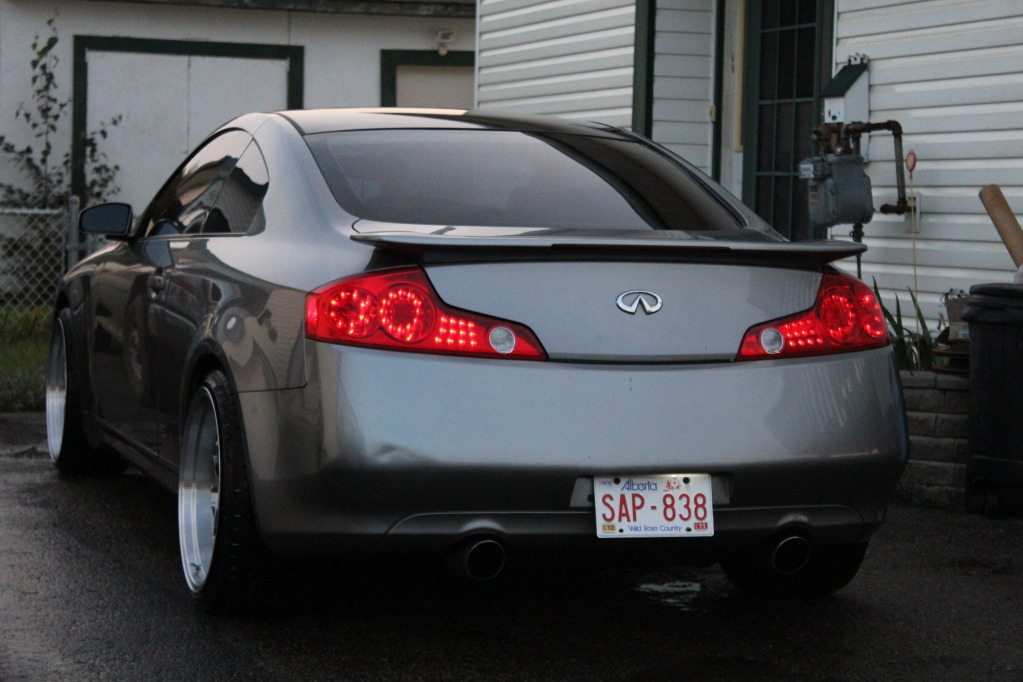
I'll take some more pics lit up when i can
Oh wow, these do look perfect. it looked off previously but that last picture looks totally perfect. thanks so much for the pics. How exactly did you plug in the extra pcb? did you just wire it up to the existing one?
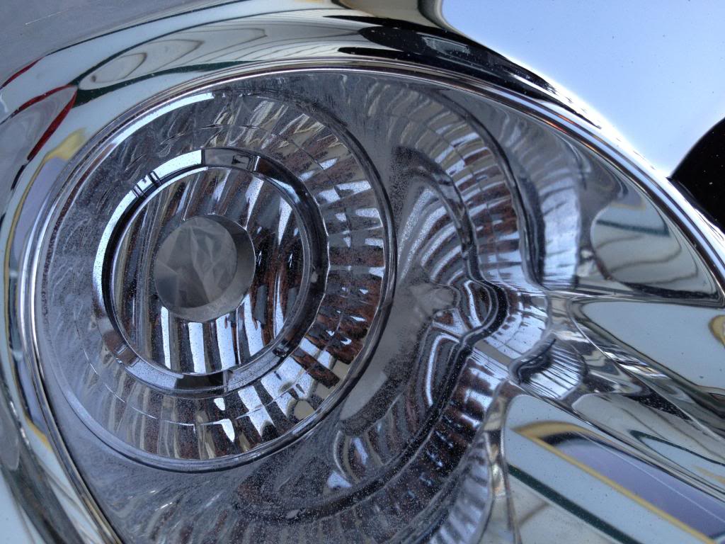
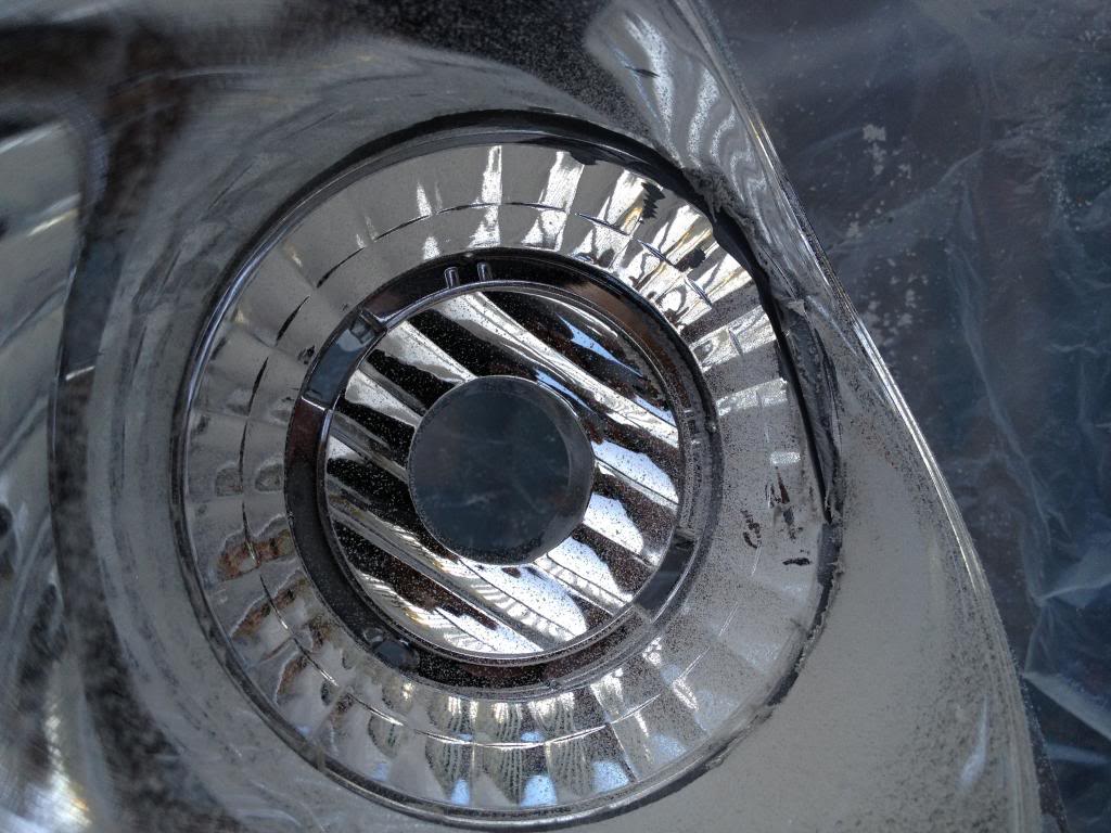
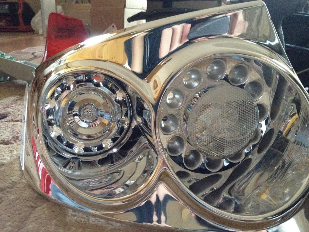
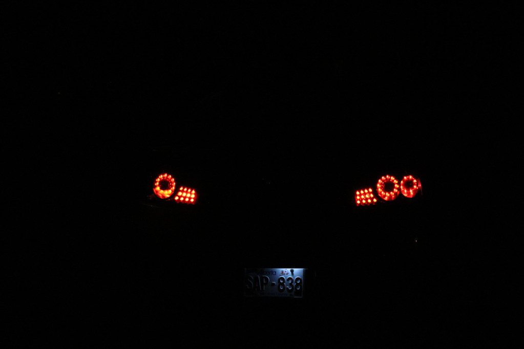
I really suck at taking pictures with my DSLR.
Look at this photo for example, even the factory OEM circle and lines dont look matching when they clearly are.
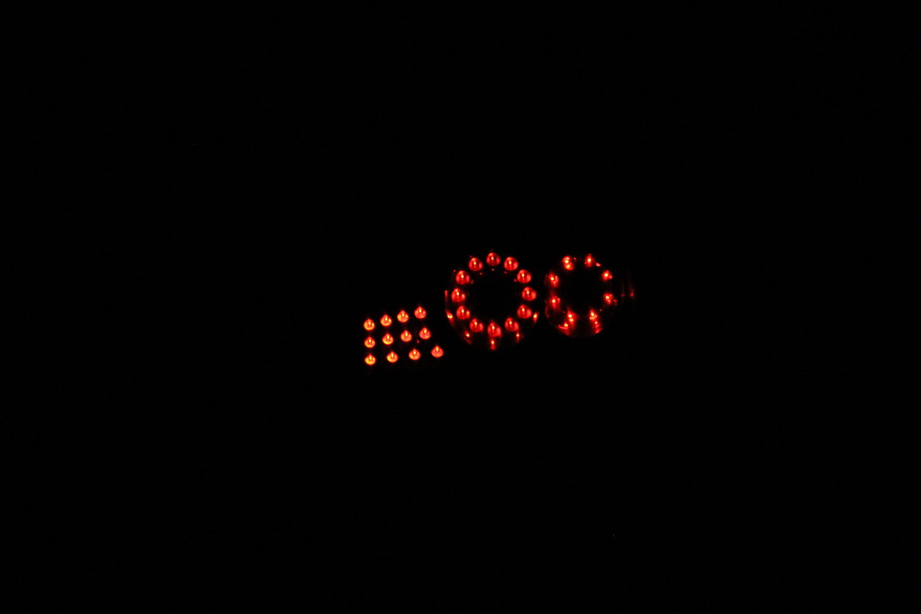
The extra circle has three wires, dim mode, bright mode and of course ground. Connect the ground to -ve battery then each of the wires to +ve to identify which one is bright which one is dim.
When you identify them, connect the dim to the side 194 bulb or even to the dim wire on the factory LED ring. and the bright one to the factory turn signal wire. ground can be at 194 bulb or turn signal bulb.
Look at this photo for example, even the factory OEM circle and lines dont look matching when they clearly are.
The extra circle has three wires, dim mode, bright mode and of course ground. Connect the ground to -ve battery then each of the wires to +ve to identify which one is bright which one is dim.
When you identify them, connect the dim to the side 194 bulb or even to the dim wire on the factory LED ring. and the bright one to the factory turn signal wire. ground can be at 194 bulb or turn signal bulb.

Registered User
iTrader: (15)
Joined: Aug 2003
Posts: 1,846
Likes: 9
From: Toh-rensa,Ahteesia,Ahcadia,Montree Pak, Longa Beacha
Trending Topics
Honestly it all depends on how creative a person is. I enjoy doing projects like this. The tails & quad bixenon definitely make the car stand out. Now I'm working on LED strips on both side markers and in license plate lights
Your help was great! you definitely made my project much easier! Sorry forgot to mention you lol I have the main post edited
Your help was great! you definitely made my project much easier! Sorry forgot to mention you lol I have the main post edited
Agreed on the quad retro that took me forever to finish... However the first tail light took me under 6 hours to do because I had no idea how and where to cut, also wiring took me some time to figure out. The second one less than 4 hours


wow what a SICK write up man,
Can you tell me how to make the light constantly on,but then brighten when step on the break? Id like to try some diff variations with my lights, but im not sure how to do that?
Can you tell me how to make the light constantly on,but then brighten when step on the break? Id like to try some diff variations with my lights, but im not sure how to do that?
He explained how to wire it all together
I can but then you wont have any turn signal. Unless you rewire the lines to the signal board then the three lines will act as a turn signal while the two rings act as running lights/brake lights