
Installing LED DRL/Foglights in bumper


Joined: Aug 2007
Posts: 1,699
Likes: 137
From: New Mexico
Installing LED DRL/Foglights in bumper
This DIY involves a hole-saw, so it’s something you need to be committed to, there’s no turning back with this one. Gotta make the usual disclaimer, do this at your own risk, I had no problems but DIY isn’t for everyone  This is a fairly simple DIY compared to painting headlights for example. The time to drill & install the lights is about equal to the time removing & re-installing the bumper. The wiring (if you follow my setup) takes about 30-45 minutes. Total DIY time should be 5 hours or less. This DIY ONLY applies to 07-09 Sedans w/ Journey bumpers, any other bumper setup will require removing the bumper first (or at the least, the plastic under-pan) & check for any obstructions.
The lights used for this DIY were selected for several reasons:
~smaller size (front to back) to allow room behind bumper mesh.
~cool running temperature to allow mounting in bumper (traditional halogen or HID fogs run quite hot, enough to melt the bumper plastic).
~complete kit, no additional relays or switches req’d.
~light weight (again, traditional fogs with their deep reflectors can be too heavy to mount securely to the bumper).
~size and flange angle of lights (these fit the mesh area well and the angle of the flange matches the bumper curve).
~Price ( source used was $82 w/ free shipping at time of DIY, other sources have them for up to $150 + shipping).
The source for the lights is~http://www.sparktecmotorsports.com/f...tm_content=pla
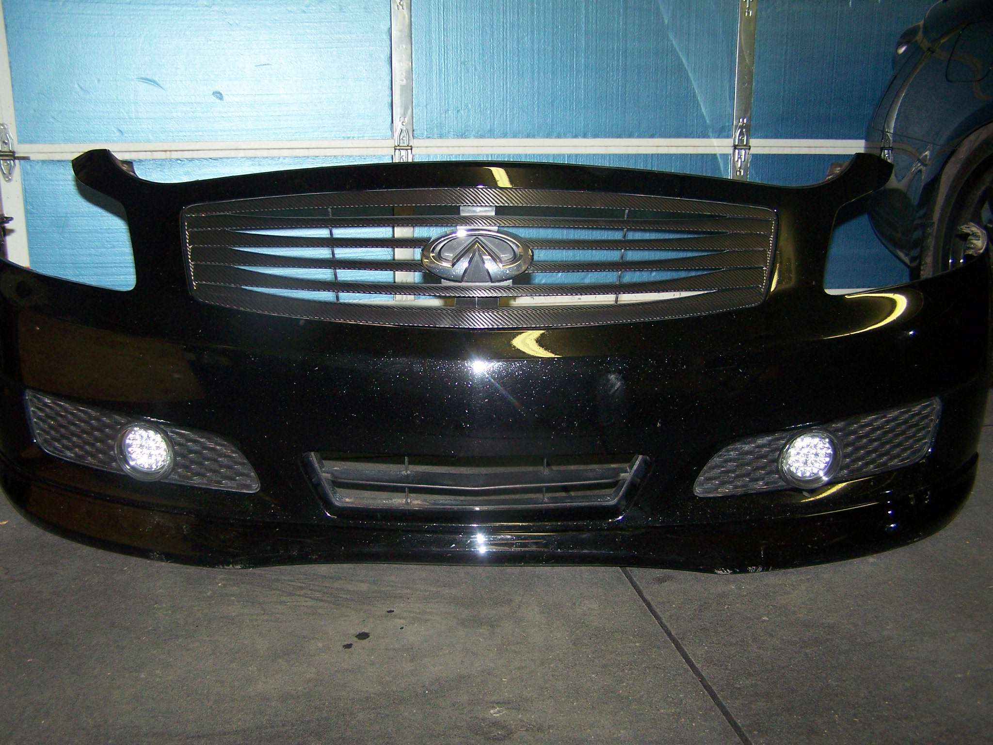
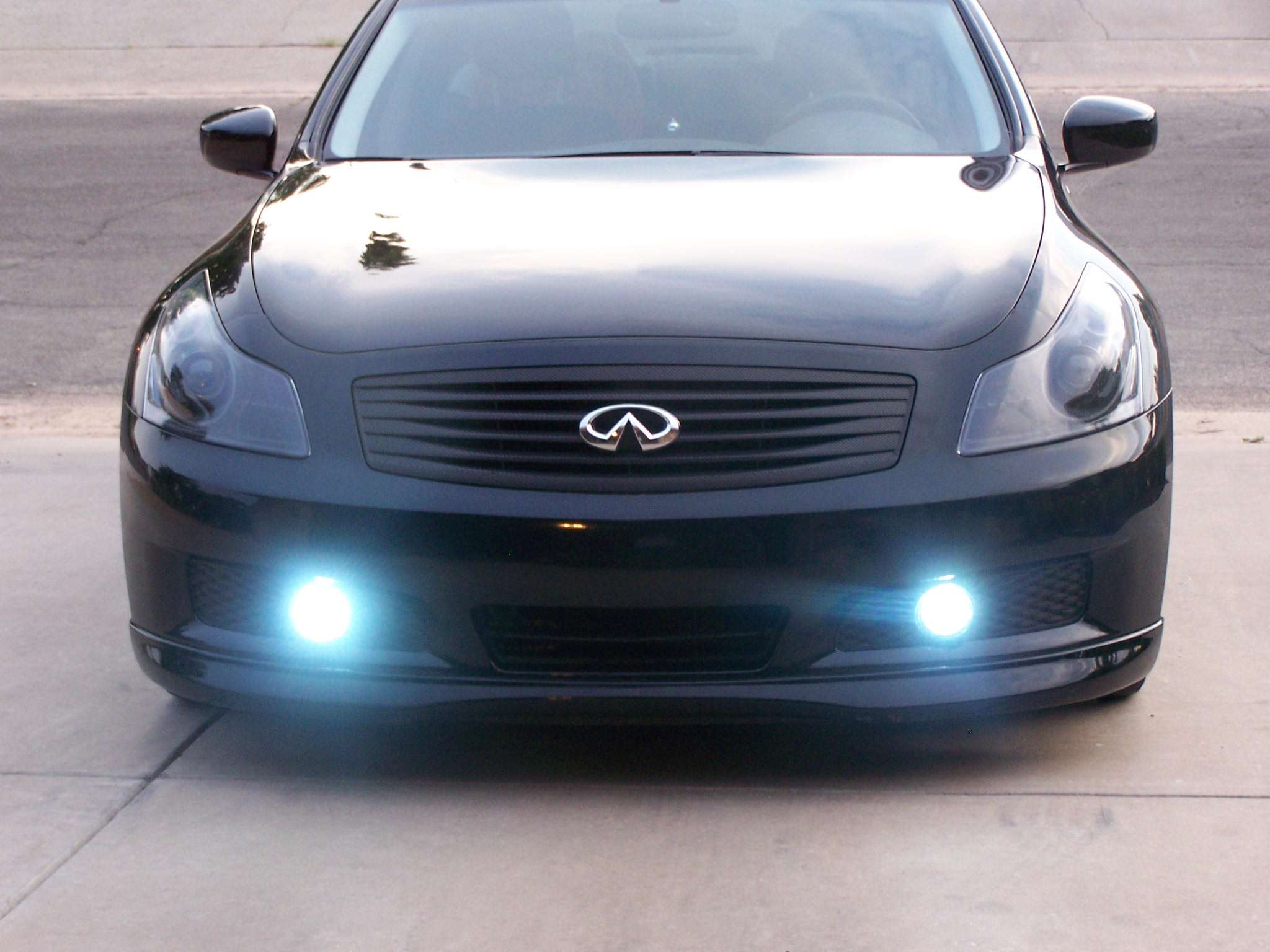
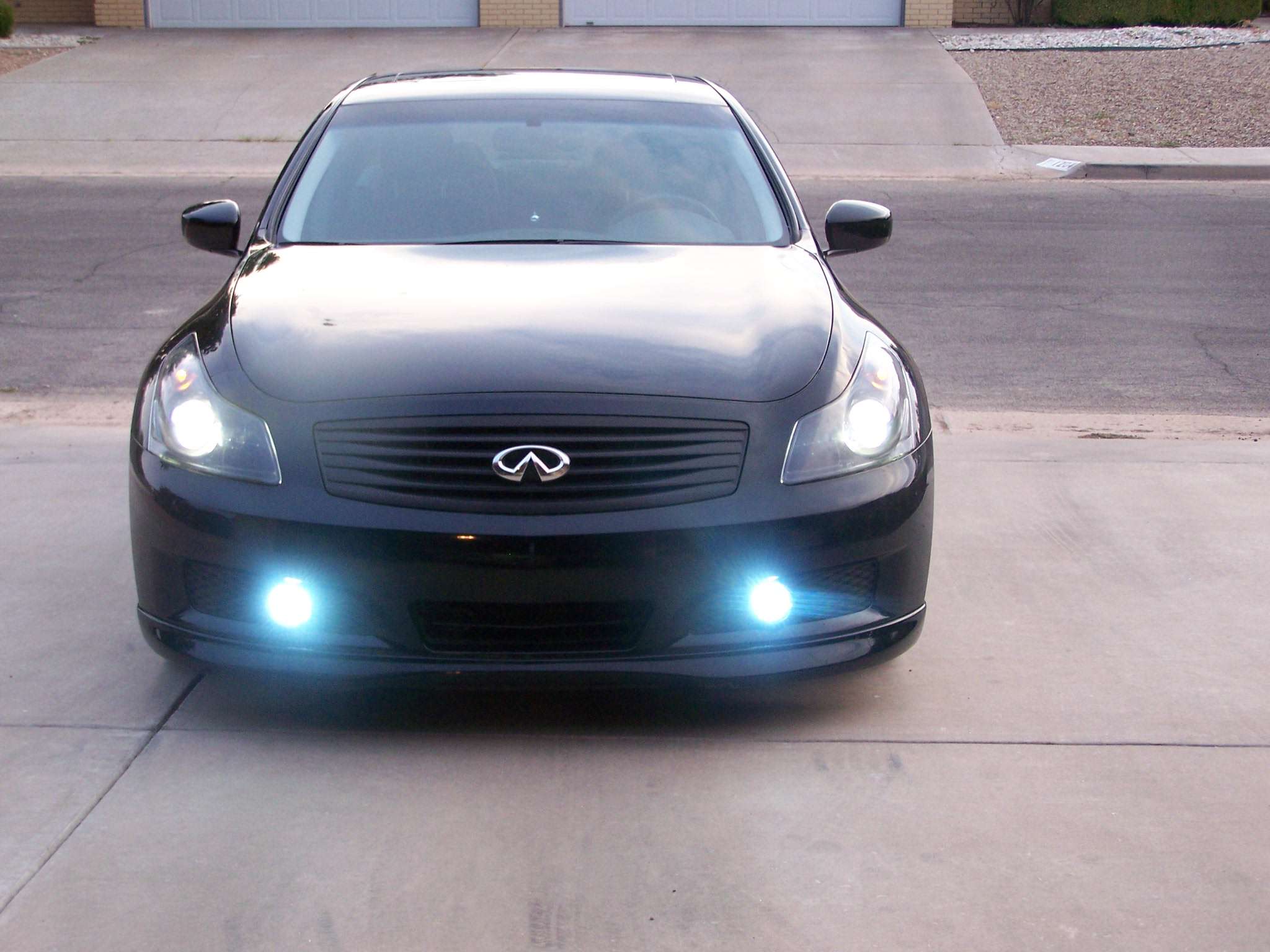
For what it’s worth I’m loving these LED lights and I wouldn’t hesitate to use them again. Some members have stated they’d prefer to have them mounted further out, but having them on a while I’m extremely happy w/ the look of the lights in the current location and if I had to do this DIY over again I’d do it all exactly the same, gotten a lot of positive comments by other drivers too
If you want the exact mounting as mine you can leave the bumper on, drill the light holes, then remove bumper, mount the lights, wire it up, then re-install bumper. If you want mounting points further out on the bumper you’ll need to check for any obstructions behind the bumper and also keep in mind the bumper curves more sharply toward the outside, so the light flange angle won’t line up as well. When doing this DIY I didn’t note the exact extra room you’ll have to slide the lights further out so it would be best to remove the under-engine splash shield and note anything that will interfere w/ light placement. Here’s a bumper removal DIY thread for an “S” model, the area behind the bumper is the same even though the S bumpers are different.
https://g35driver.com/forums/v36-interior-exterior-lighting/197930-diy-2007-g35s-front-bumper-removal.html
You’ll notice the washer fluid tank and the two plastic pieces (one on each side) that can interfere. My mount location goes to the left of both plastic pieces. If you go further out you may run into the right plastic piece and the washer tank on the left.
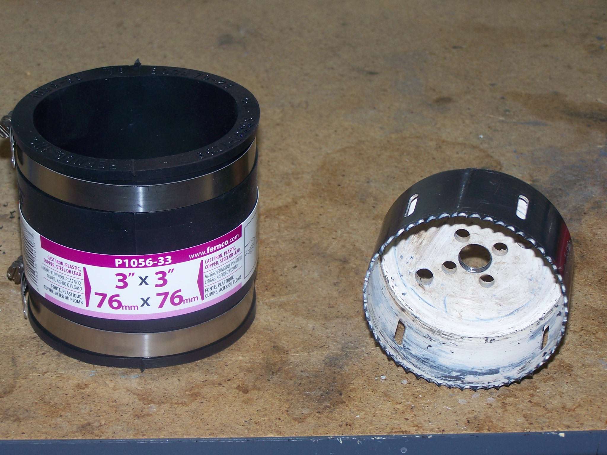
You’ll need a 3.5” hole saw and a 3” rubber pipe sleeve (for plumbing repair) w/ included hose clamps. Holesaws run about $17 at Home Depot and the drill shank is another $15, if you know a plumber they typically have these in their tool collection or possibly a rental shop may have one to rent for much cheaper than buying one just for this project. Black RTV Silicone is optional.
Before doing any measuring or cutting just do a test wire to make sure your light kit is functioning properly. Connect the lights to the other terminals that have the clear plastic wire sleeves (black to black and white to yellow) push the switch connector together and you’ll have (2) Red wires and (2) black wires. Just put the red wires to the car battery positive terminal and the black wires to the negative terminal (get a helper if you can’t hold the wires together by yourself ) and you should get light, if not the switch may be in the “off” mode (switch will glow red), if so, push the switch and the lights should be on & the switch will glow green. Disconnect the switch from the rest of the wiring, you won’t need it again until the end. If all is good then proceed, if not, start swearing & contact the vendor.
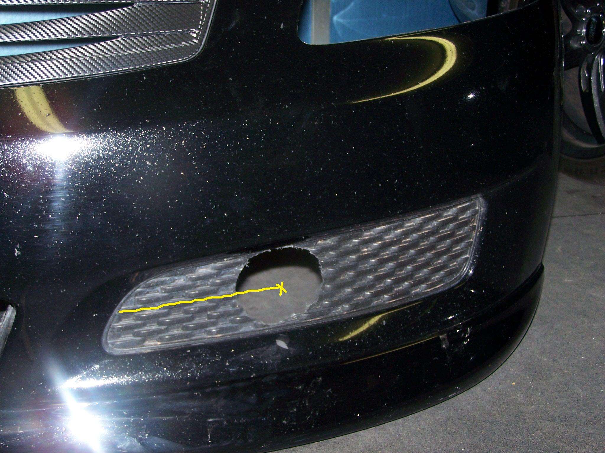
Looking at this pic of the bumper and the hole cutouts (I don’t have pics of me actually cutting the holes w/ the bumper on, sorry)
The center point for the hole saw drill bit (should be a 1/4” bit) is 6 3/4” from the left side center of the mesh to the center point (top to bottom) see yellow line for reference.
Punch the center point so you can get a good start for a pilot hole, I’d start w/ a 1/8” bit, then go w/ a 1/4” bit, the mesh cuts like butter w/ the hole saw so you want to get the pilot hole identical to the hole saw drill bit size so the hole saw will start true. You MUST have the drill point in the exact center (top to bottom) of the mesh, A good way to determine exact center is get a toothpick and mark aprox center and then flip toothpick around and see if the center lines up, if not mark a new line, flip the toothpick until you get the same line from both sides (hope that makes sense). The hole saw cuts fast so you need to hold the drill firm and don’t let it wobble on you. The KEY to getting a straight mount is the accuracy of your drilling. You must have the car on a level surface and have the car parked straight, this will get you the level and light beam lines you’ll need to get the fogs mounted right. Once you get the pilot hole drilled you’ll want to get your drill level, and straight w/ the cars’ side. Get a shoebox propped high enough so the top of the box is level w/ your level drill. The long outside end of the shoebox should be along the side of the cars’ straight line. If you have a 2x4 that you can run along your straight-parked car it’ll make the line more accurate, look down the 2x4 from a distance to insure that it is indeed straight down the car.
Align the box to the 2x4 and you’ll have both visual axis needed for a true drill hole. Just keep the drill steady, straight and level and you’ll be fine. Push it firmly into the mesh but let the saw do the work, don’t force it hard but apply steady pressure through the mesh. BE SURE to let the saw stop before removing it from the mesh or you might nick the bumper w/ a spinning saw on the way out. Also, once through the hole stop pushing the saw, there’s not a lot of room back there and you don’t want anything else to get cut. Once the hole is cut you’ll notice a lot of plastic shards around the hole, most should just come of by rubbing them but you might need a sharp utility knife if not. Repeat shoebox procedure for other side and drill other hole.
Continued...........
The lights used for this DIY were selected for several reasons:
~smaller size (front to back) to allow room behind bumper mesh.
~cool running temperature to allow mounting in bumper (traditional halogen or HID fogs run quite hot, enough to melt the bumper plastic).
~complete kit, no additional relays or switches req’d.
~light weight (again, traditional fogs with their deep reflectors can be too heavy to mount securely to the bumper).
~size and flange angle of lights (these fit the mesh area well and the angle of the flange matches the bumper curve).
~Price ( source used was $82 w/ free shipping at time of DIY, other sources have them for up to $150 + shipping).
The source for the lights is~http://www.sparktecmotorsports.com/f...tm_content=pla
For what it’s worth I’m loving these LED lights and I wouldn’t hesitate to use them again. Some members have stated they’d prefer to have them mounted further out, but having them on a while I’m extremely happy w/ the look of the lights in the current location and if I had to do this DIY over again I’d do it all exactly the same, gotten a lot of positive comments by other drivers too
If you want the exact mounting as mine you can leave the bumper on, drill the light holes, then remove bumper, mount the lights, wire it up, then re-install bumper. If you want mounting points further out on the bumper you’ll need to check for any obstructions behind the bumper and also keep in mind the bumper curves more sharply toward the outside, so the light flange angle won’t line up as well. When doing this DIY I didn’t note the exact extra room you’ll have to slide the lights further out so it would be best to remove the under-engine splash shield and note anything that will interfere w/ light placement. Here’s a bumper removal DIY thread for an “S” model, the area behind the bumper is the same even though the S bumpers are different.
https://g35driver.com/forums/v36-interior-exterior-lighting/197930-diy-2007-g35s-front-bumper-removal.html
You’ll notice the washer fluid tank and the two plastic pieces (one on each side) that can interfere. My mount location goes to the left of both plastic pieces. If you go further out you may run into the right plastic piece and the washer tank on the left.
You’ll need a 3.5” hole saw and a 3” rubber pipe sleeve (for plumbing repair) w/ included hose clamps. Holesaws run about $17 at Home Depot and the drill shank is another $15, if you know a plumber they typically have these in their tool collection or possibly a rental shop may have one to rent for much cheaper than buying one just for this project. Black RTV Silicone is optional.
Before doing any measuring or cutting just do a test wire to make sure your light kit is functioning properly. Connect the lights to the other terminals that have the clear plastic wire sleeves (black to black and white to yellow) push the switch connector together and you’ll have (2) Red wires and (2) black wires. Just put the red wires to the car battery positive terminal and the black wires to the negative terminal (get a helper if you can’t hold the wires together by yourself ) and you should get light, if not the switch may be in the “off” mode (switch will glow red), if so, push the switch and the lights should be on & the switch will glow green. Disconnect the switch from the rest of the wiring, you won’t need it again until the end. If all is good then proceed, if not, start swearing & contact the vendor.
Looking at this pic of the bumper and the hole cutouts (I don’t have pics of me actually cutting the holes w/ the bumper on, sorry)
The center point for the hole saw drill bit (should be a 1/4” bit) is 6 3/4” from the left side center of the mesh to the center point (top to bottom) see yellow line for reference.
Punch the center point so you can get a good start for a pilot hole, I’d start w/ a 1/8” bit, then go w/ a 1/4” bit, the mesh cuts like butter w/ the hole saw so you want to get the pilot hole identical to the hole saw drill bit size so the hole saw will start true. You MUST have the drill point in the exact center (top to bottom) of the mesh, A good way to determine exact center is get a toothpick and mark aprox center and then flip toothpick around and see if the center lines up, if not mark a new line, flip the toothpick until you get the same line from both sides (hope that makes sense). The hole saw cuts fast so you need to hold the drill firm and don’t let it wobble on you. The KEY to getting a straight mount is the accuracy of your drilling. You must have the car on a level surface and have the car parked straight, this will get you the level and light beam lines you’ll need to get the fogs mounted right. Once you get the pilot hole drilled you’ll want to get your drill level, and straight w/ the cars’ side. Get a shoebox propped high enough so the top of the box is level w/ your level drill. The long outside end of the shoebox should be along the side of the cars’ straight line. If you have a 2x4 that you can run along your straight-parked car it’ll make the line more accurate, look down the 2x4 from a distance to insure that it is indeed straight down the car.
Align the box to the 2x4 and you’ll have both visual axis needed for a true drill hole. Just keep the drill steady, straight and level and you’ll be fine. Push it firmly into the mesh but let the saw do the work, don’t force it hard but apply steady pressure through the mesh. BE SURE to let the saw stop before removing it from the mesh or you might nick the bumper w/ a spinning saw on the way out. Also, once through the hole stop pushing the saw, there’s not a lot of room back there and you don’t want anything else to get cut. Once the hole is cut you’ll notice a lot of plastic shards around the hole, most should just come of by rubbing them but you might need a sharp utility knife if not. Repeat shoebox procedure for other side and drill other hole.
Continued...........
Last edited by blnewt; Dec 28, 2012 at 10:01 PM.
Joined: Aug 2007
Posts: 1,699
Likes: 137
From: New Mexico
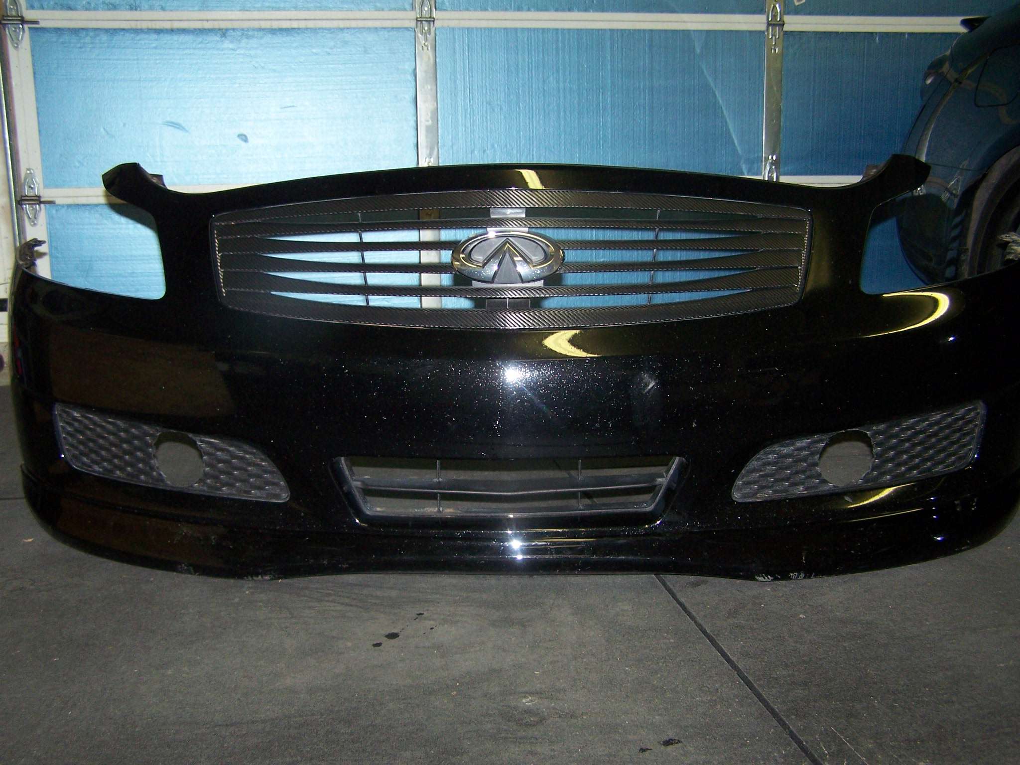
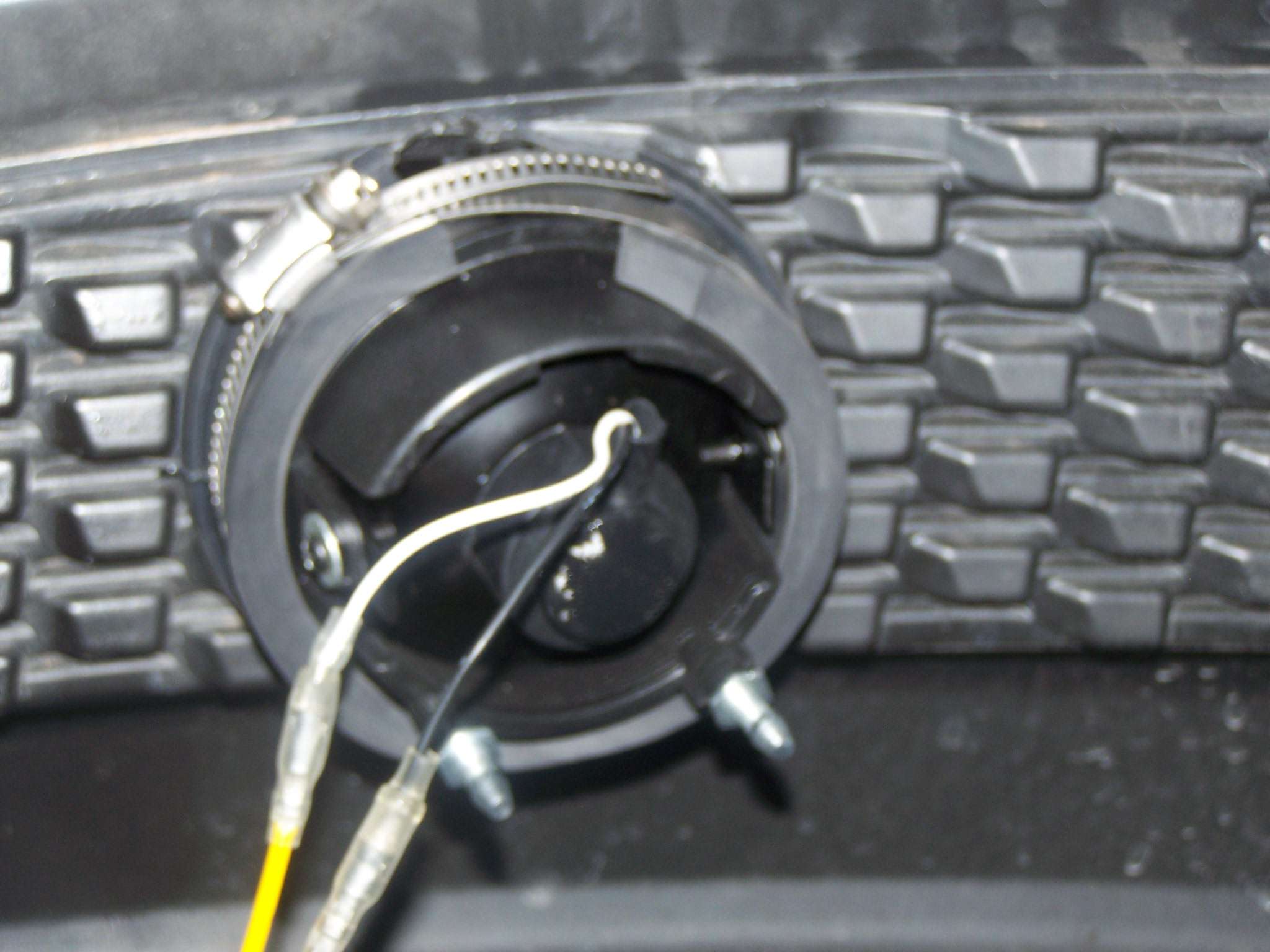
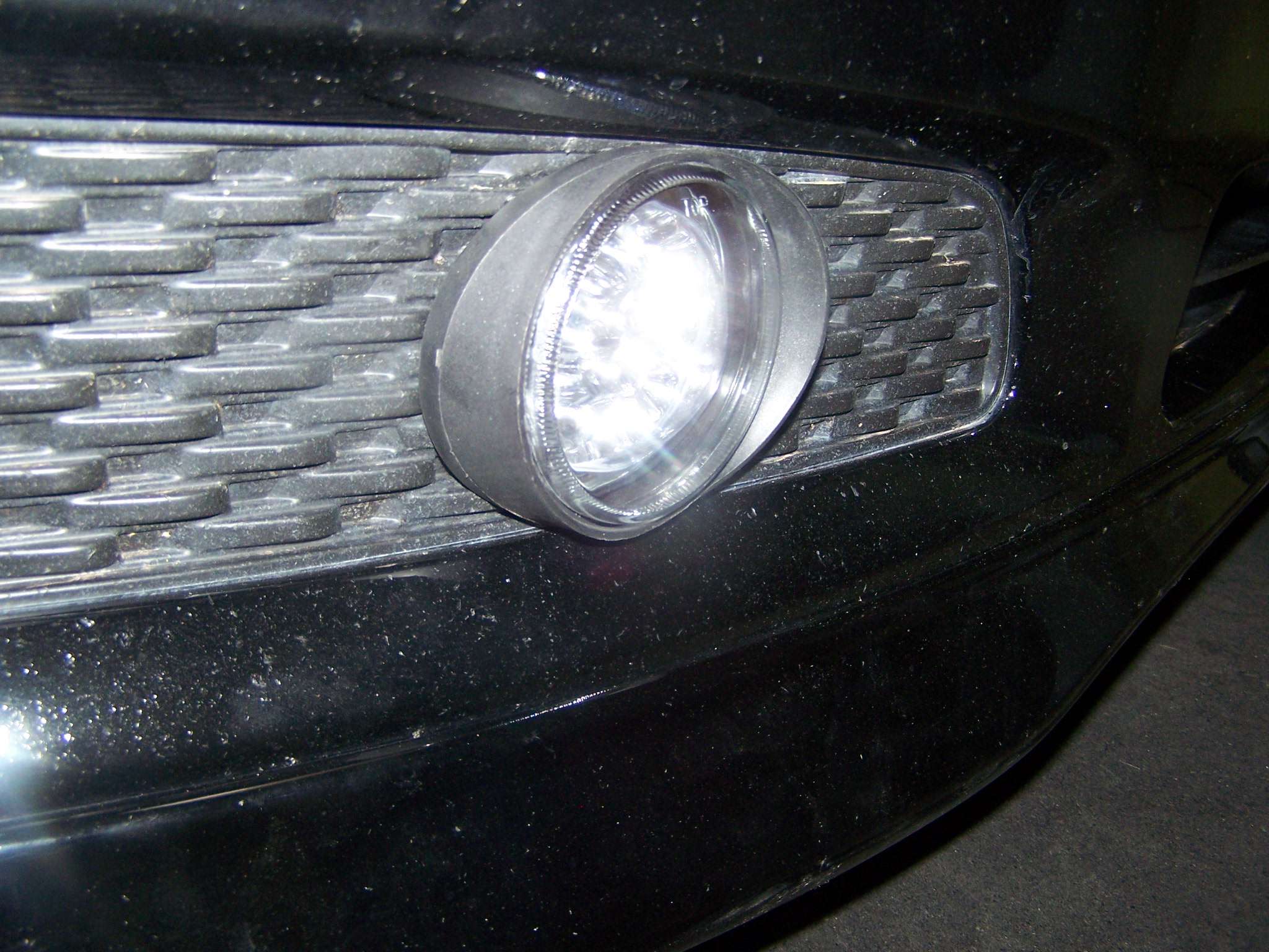
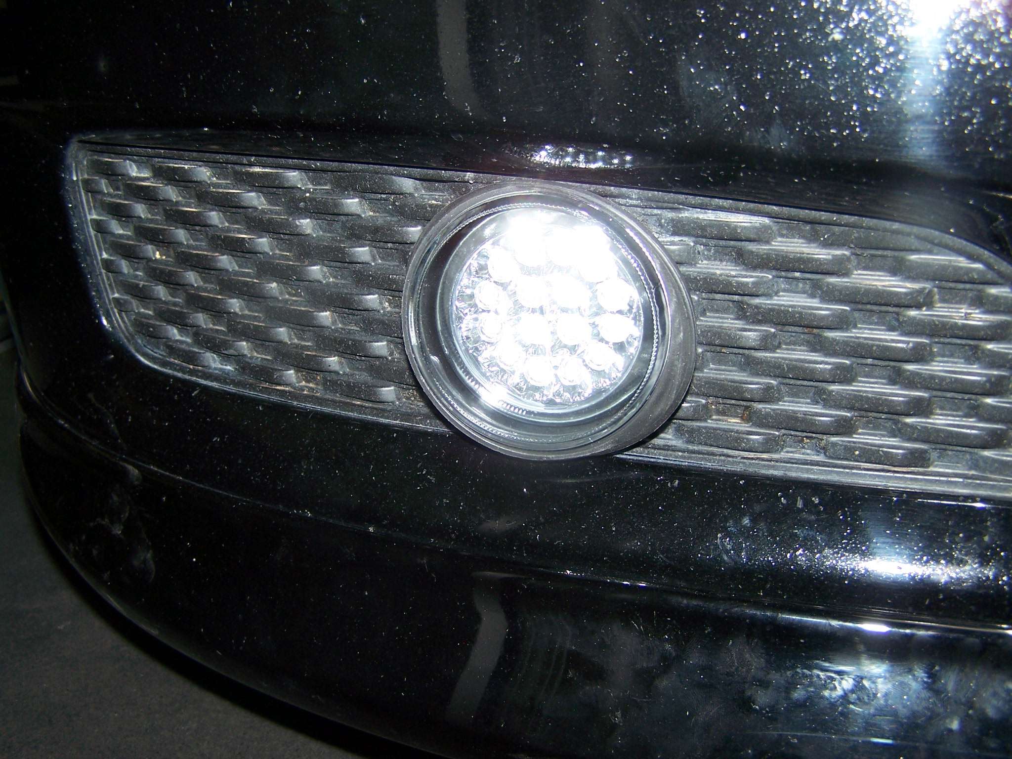
Place the correct side light in the hole w/ the �top� printed on the lens facing up, do the same w/ the other side light. Just see how they fit and if any additional trimming is needed. I didn�t trim any more around my holes, and didn�t have any significant gaps. Once you�re satisfied w/ how the lights fit then you�ll need to cut the rubber support rings. The 3� rubber sleeve has hose clamps included (about $6 at Home Depot), just cut the sleeve inside the hose clamp on each end, you�ll end up w/ (2) 1 1/4� wide pieces, so essentially you�ll be cutting out the center section of the sleeve leaving the two ends (w/ the little recessed channel that the clamps rest in) to use for your two light support rings. Once you have the two rings cut you�ll slice a 3/4� section from the ring making the rings� diameter smaller. Prior to mounting the ring on the light you might want to run a bead of black RTV silicone around the back of the mesh where the light meets the mesh, I didn�t do this but it will be another layer of insurance for a tight fit, and if you have any gaps around the light hole this will seal them as well. If you do decide to use silicone you might want to wire the lights while you let the silicone dry up a bit before applying the rubber rings. Be sure to have the silicone flush to the mesh, you want a flush area for the rubber ring to rest on.
Just press the light firmly against the mesh making sure to keep the light in the proper place, you want both lights to be aiming straight ahead and
both lights on the same level. When you�re sure you have the light in the right place push the rubber tightly against the mesh and tighten up the clamp, if you can�t keep the light tight against the mesh while securing the rubber ring you should get a helper to give you a hand. If you didn�t use silicone and just can�t get the light to sit just right you may want to go ahead and use silicone.
Now it�s time to begin wiring the unit. My G37 only has the premium package so the fuse section I used may not be available on your car so be sure to check, or if you have a better hot lead to tap into so much the better.
This wiring allows the lights to be turned off & on whenever you want, it�s not tied into any Infiniti switch, the only thing you want to be sure of is you wire it to a source that is only hot when the start button is activated and off when you turn off the car. If you just wire it to a 12v source you may end up leaving the lights on and running down your battery by mistake. The place I tied into isn�t the tidiest connection but it�s a great spot since it�s so easy to connect to and is only hot when the car is �awake� (the motor isn�t running, but the start button is pushed, radio on, etc.). I was leery of tapping into a wire in the main power box (to the left side of the battery) as I may overload an existing circuit or just screw up something along the way. Here�s the fuse box in the drivers side kick panel and the place I tapped in~
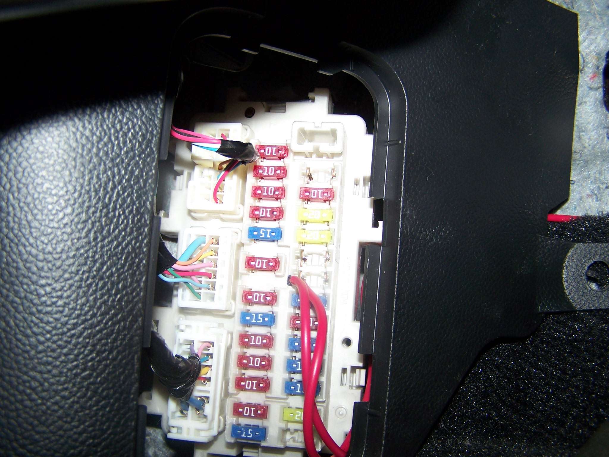
It�s the 6th fuse block down on the right column and the left side connector. Be sure to use a voltmeter to confirm for your vehicle if this is the place you want to tie into as well. If this fuse is used for your particular G you�ll have to do some searching for an alternate location. I wish I had more sources but couldn�t get much help w/ this
Start by running the harness down between the passenger headlight (yellow line) down to the passenger DRL, keeping the bumper a couple inches away from the car, leave enough wire to the passenger DRL to connect it w/ a little slack, then run the wire under the plastic vertical piece (just to the right of the DRL) and over to the drivers DRL. Use zip ties to keep the wire tied to the lower front frame area.Here�s the pics of the remaining wiring~
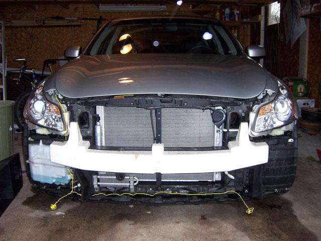
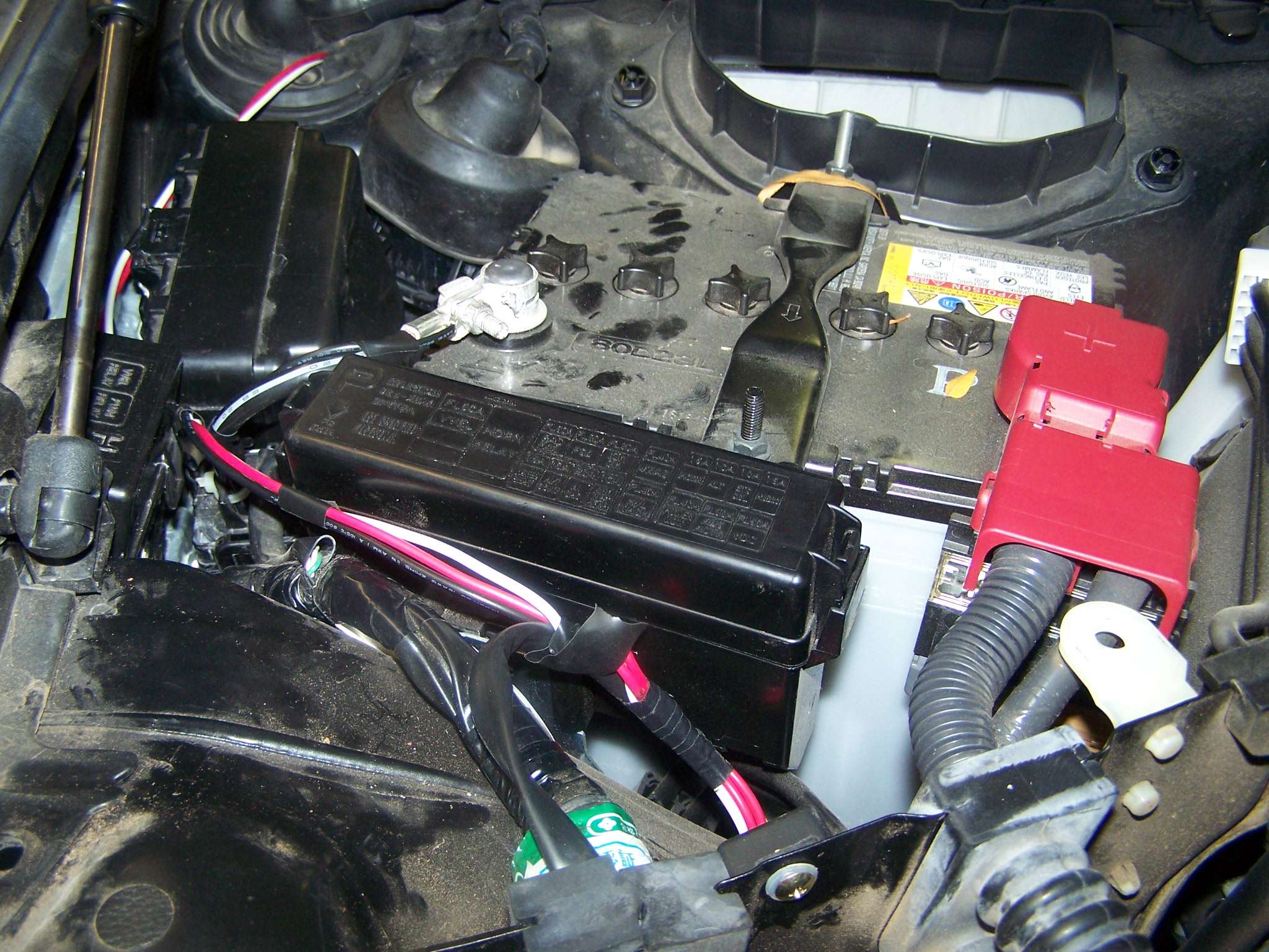
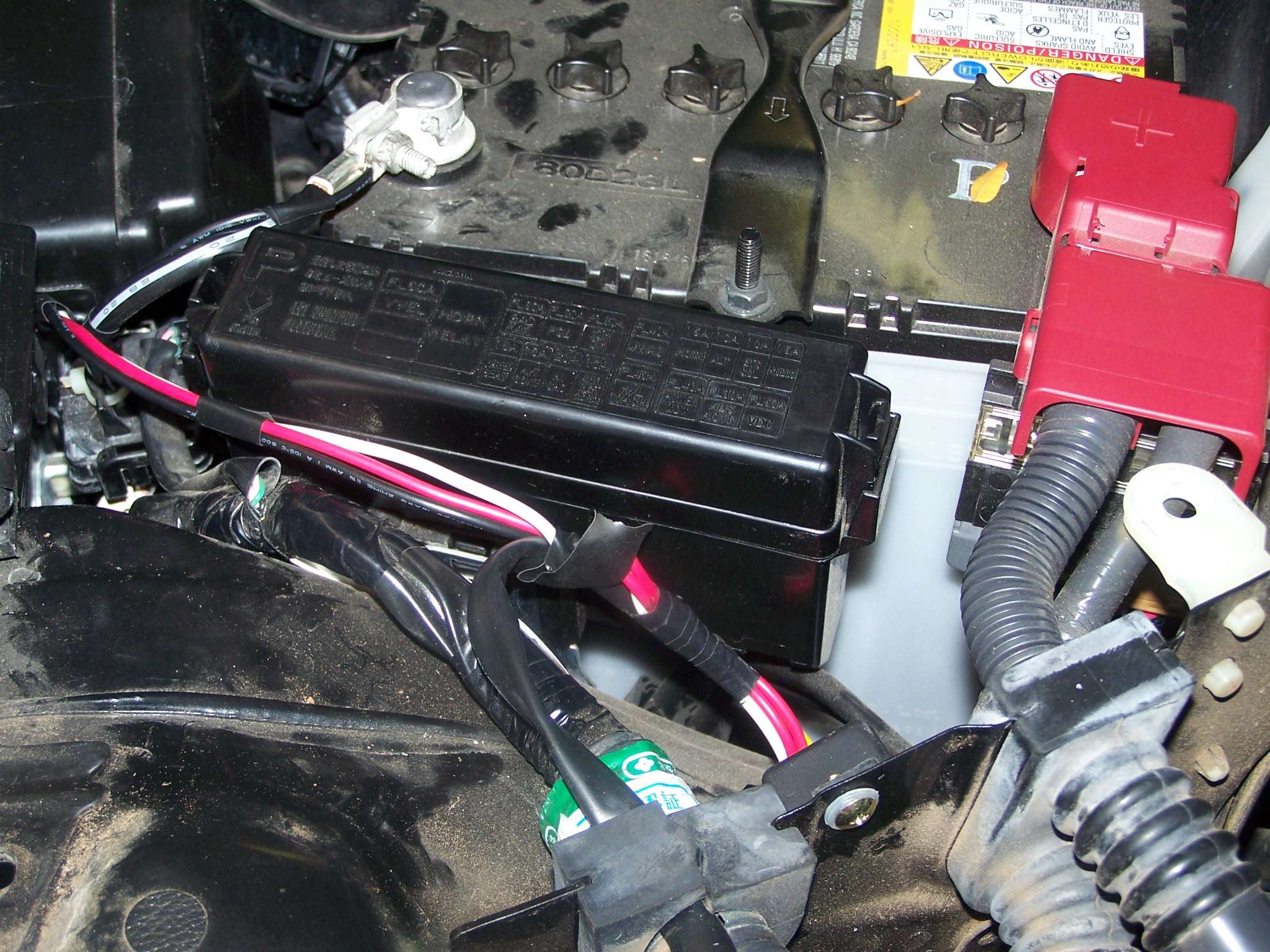
I run the harness up from the passenger headlight along the existing main harness (w/ a couple zip ties). I mount the relay to the inside wall of the battery cover (right to the right of the black rectangle fuse box) and just let the fuse rest below the relay. I then connect the single black wire to the negative battery terminal (the other black wire from the switch goes inside the car and grounds to below the steering wheel).
I then was lucky enough to find a thread that suggested using the passenger side harness bulkhead boot to get through the firewall & into the cabin.
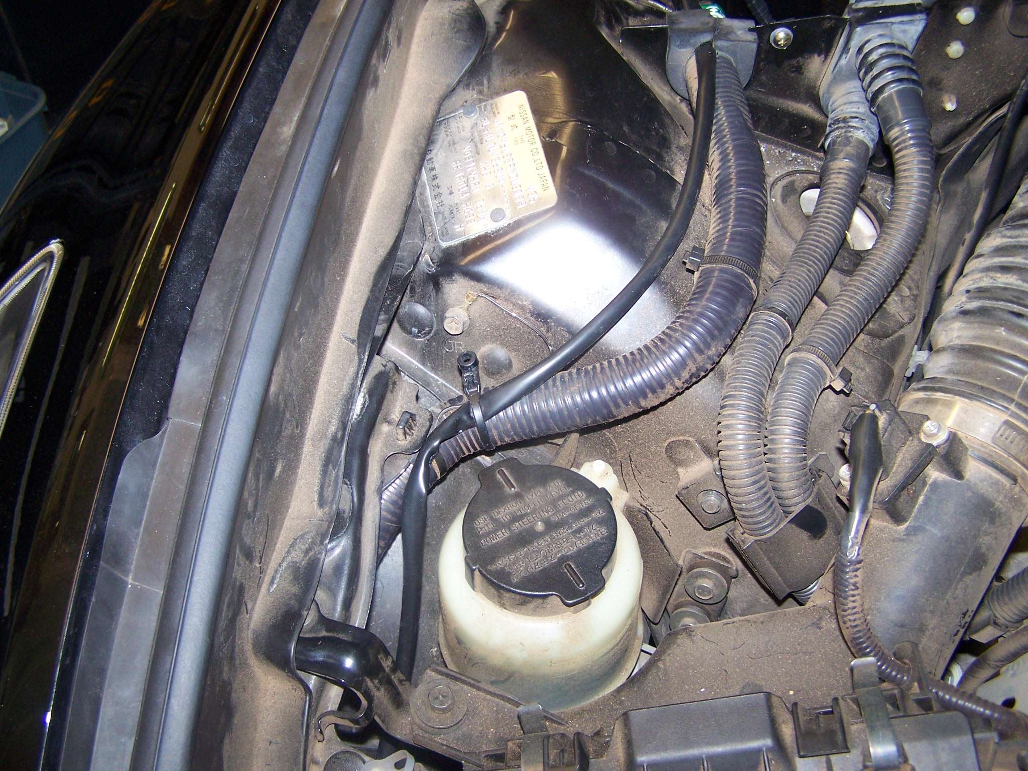
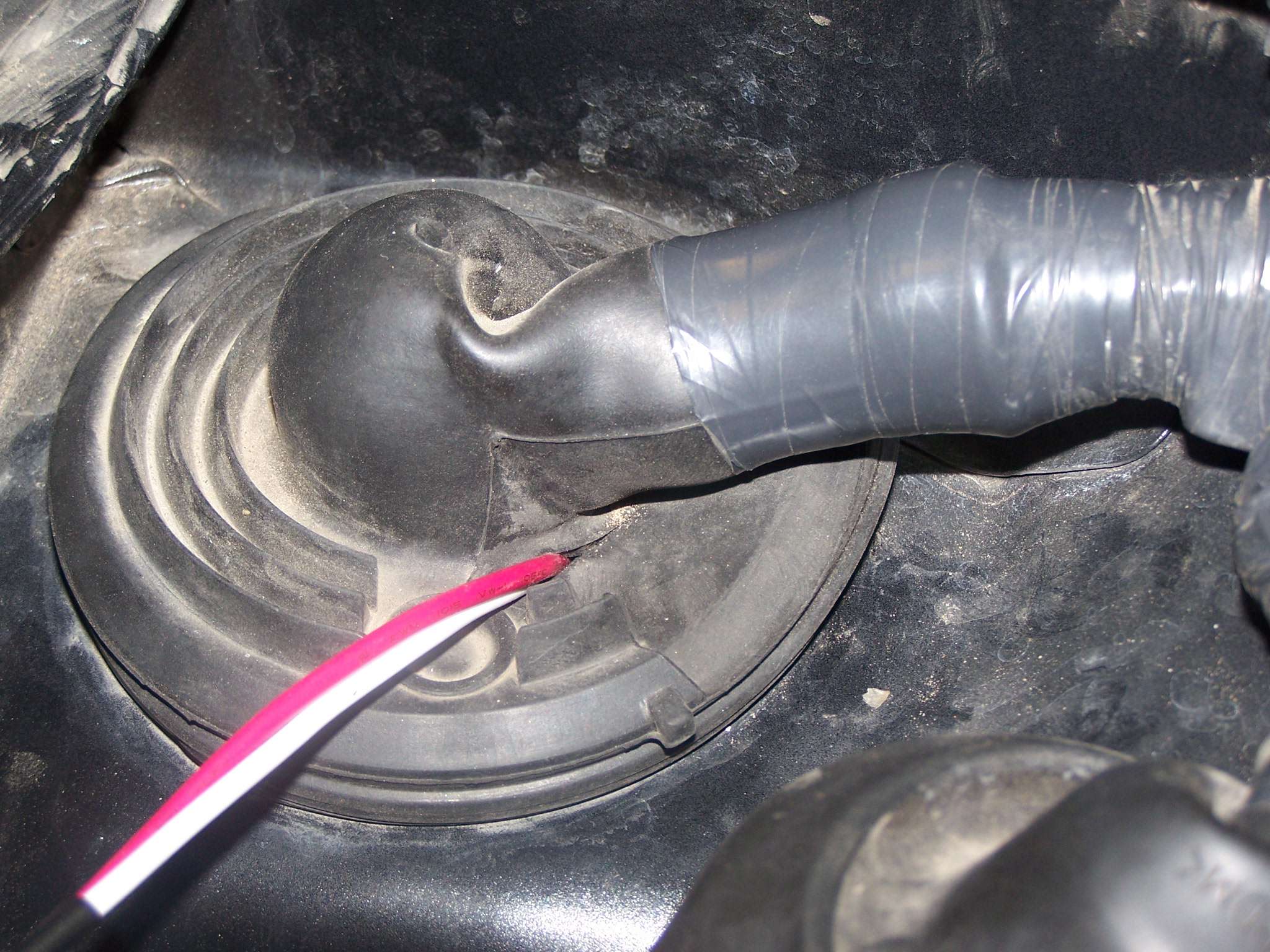
You just cut a 1� slit into the boot in front of the harness entry (my slit is a bit close to the main harness, I�d go out about a 1/4� just to be sure you don�t nick any wires in the harness (I didn�t thankfully), you�ll have to pull part of the boot up to see where to thread the wires down the hole. The boot is a pain to get back on it�s perch so only pull up enough to get a look down there. You�ll be pushing the white switch terminal (the actual switch and it�s wires should be disconnected, you�ll re-connect these inside the cabin) and wires through the boot. Push the terminal in first and the rest will be easy.
In order to have access inside the cabin to route the wires you�ll need to remove the glovebox, here�s a good DIY for that, and if you haven�t changed your in-cabin micro filter now is a good time to knock that off too
https://g35driver.com/forums/v36-diy/302320-diy-replacing-cabin-microfilter.html
It will help if you can have a helper shine a light through the partially open boot so you can see where the wires will be coming from. The red pronged lead will be too short to run all the way to the fuse box so you�ll want to splice it to the red wire that comes from the switch connector. Be sure to solder the wires after joining and use a crimp termination cap or at least a wire nut w/ electrical tape to protect the splice. After splicing the red wires you�ll run the wires behind the radio area (again, have a light on the drivers side footwell shining behind the radio area so you can see the gap that you can run the wires through. I used a long screwdriver and taped the white connector to the end of the screwdriver to run the wire group behind the radio. There was plenty of room back there you just need something long enough to thread it through. Once you get the wires through you�ll want to anchor your pronged black ground wire. Just loosen the lower left nut below the steering column against the firewall and put the pronged terminal under the nut & tighten it back up. Then cut the middle of the red wire (so you�ll have the longest wires to get to the fuse box) and just twist the two red wires together and solder (so you have a single soldered wire tip to go into the fuse clamp. Run your red wire behind the fuse box cover and into the fuse box and wedge the wire between the fuse clamp and the plastic wall, it should be firmly in place. You now can connect the switch, I found a convenient and out of the way spot, it�s an unused switch panel to the right of the hood release lever, see pic below.
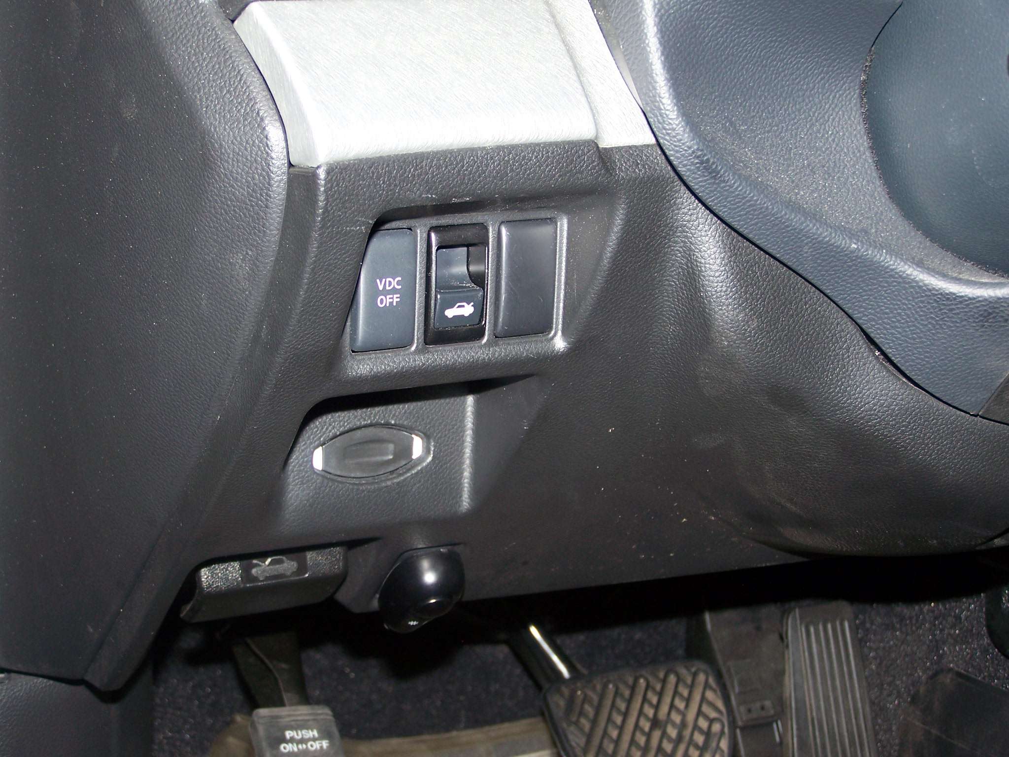
I like the spot because it�s easy to find but the glowing LED from the switch isn�t distracting down there. The two sided tape for the switch isn�t too strong so I may have to get stronger tape later, we�ll see. Once you�re happy w/ the connections, place the remaining wire between the black floor trim and the padded firewall insulation to hide it from view, and tape up the wire on the passenger side to keep it behind the glovebox line of sight and away from any area that could come in contact from the passengers feet. Zip tie the switch wire to keep it snug and tuck the remaining switch wire behind the emergency brake bracket and firewall.
Continued.........
Just press the light firmly against the mesh making sure to keep the light in the proper place, you want both lights to be aiming straight ahead and
both lights on the same level. When you�re sure you have the light in the right place push the rubber tightly against the mesh and tighten up the clamp, if you can�t keep the light tight against the mesh while securing the rubber ring you should get a helper to give you a hand. If you didn�t use silicone and just can�t get the light to sit just right you may want to go ahead and use silicone.
Now it�s time to begin wiring the unit. My G37 only has the premium package so the fuse section I used may not be available on your car so be sure to check, or if you have a better hot lead to tap into so much the better.
This wiring allows the lights to be turned off & on whenever you want, it�s not tied into any Infiniti switch, the only thing you want to be sure of is you wire it to a source that is only hot when the start button is activated and off when you turn off the car. If you just wire it to a 12v source you may end up leaving the lights on and running down your battery by mistake. The place I tied into isn�t the tidiest connection but it�s a great spot since it�s so easy to connect to and is only hot when the car is �awake� (the motor isn�t running, but the start button is pushed, radio on, etc.). I was leery of tapping into a wire in the main power box (to the left side of the battery) as I may overload an existing circuit or just screw up something along the way. Here�s the fuse box in the drivers side kick panel and the place I tapped in~
It�s the 6th fuse block down on the right column and the left side connector. Be sure to use a voltmeter to confirm for your vehicle if this is the place you want to tie into as well. If this fuse is used for your particular G you�ll have to do some searching for an alternate location. I wish I had more sources but couldn�t get much help w/ this
Start by running the harness down between the passenger headlight (yellow line) down to the passenger DRL, keeping the bumper a couple inches away from the car, leave enough wire to the passenger DRL to connect it w/ a little slack, then run the wire under the plastic vertical piece (just to the right of the DRL) and over to the drivers DRL. Use zip ties to keep the wire tied to the lower front frame area.Here�s the pics of the remaining wiring~
I run the harness up from the passenger headlight along the existing main harness (w/ a couple zip ties). I mount the relay to the inside wall of the battery cover (right to the right of the black rectangle fuse box) and just let the fuse rest below the relay. I then connect the single black wire to the negative battery terminal (the other black wire from the switch goes inside the car and grounds to below the steering wheel).
I then was lucky enough to find a thread that suggested using the passenger side harness bulkhead boot to get through the firewall & into the cabin.
You just cut a 1� slit into the boot in front of the harness entry (my slit is a bit close to the main harness, I�d go out about a 1/4� just to be sure you don�t nick any wires in the harness (I didn�t thankfully), you�ll have to pull part of the boot up to see where to thread the wires down the hole. The boot is a pain to get back on it�s perch so only pull up enough to get a look down there. You�ll be pushing the white switch terminal (the actual switch and it�s wires should be disconnected, you�ll re-connect these inside the cabin) and wires through the boot. Push the terminal in first and the rest will be easy.
In order to have access inside the cabin to route the wires you�ll need to remove the glovebox, here�s a good DIY for that, and if you haven�t changed your in-cabin micro filter now is a good time to knock that off too
https://g35driver.com/forums/v36-diy/302320-diy-replacing-cabin-microfilter.html
It will help if you can have a helper shine a light through the partially open boot so you can see where the wires will be coming from. The red pronged lead will be too short to run all the way to the fuse box so you�ll want to splice it to the red wire that comes from the switch connector. Be sure to solder the wires after joining and use a crimp termination cap or at least a wire nut w/ electrical tape to protect the splice. After splicing the red wires you�ll run the wires behind the radio area (again, have a light on the drivers side footwell shining behind the radio area so you can see the gap that you can run the wires through. I used a long screwdriver and taped the white connector to the end of the screwdriver to run the wire group behind the radio. There was plenty of room back there you just need something long enough to thread it through. Once you get the wires through you�ll want to anchor your pronged black ground wire. Just loosen the lower left nut below the steering column against the firewall and put the pronged terminal under the nut & tighten it back up. Then cut the middle of the red wire (so you�ll have the longest wires to get to the fuse box) and just twist the two red wires together and solder (so you have a single soldered wire tip to go into the fuse clamp. Run your red wire behind the fuse box cover and into the fuse box and wedge the wire between the fuse clamp and the plastic wall, it should be firmly in place. You now can connect the switch, I found a convenient and out of the way spot, it�s an unused switch panel to the right of the hood release lever, see pic below.
I like the spot because it�s easy to find but the glowing LED from the switch isn�t distracting down there. The two sided tape for the switch isn�t too strong so I may have to get stronger tape later, we�ll see. Once you�re happy w/ the connections, place the remaining wire between the black floor trim and the padded firewall insulation to hide it from view, and tape up the wire on the passenger side to keep it behind the glovebox line of sight and away from any area that could come in contact from the passengers feet. Zip tie the switch wire to keep it snug and tuck the remaining switch wire behind the emergency brake bracket and firewall.
Continued.........
Joined: Aug 2007
Posts: 1,699
Likes: 137
From: New Mexico
Now you can re-install the glove box, reattach bumper (be sure to have a couple cloths wrapped over the bumper where it meets the fenders or you might scratch the paint) & enjoy your new LEDs
PM me with any further questions or details.
Brad
PM me with any further questions or details.
Brad
Last edited by blnewt; Aug 24, 2012 at 07:56 PM.

Joined: Aug 2007
Posts: 1,699
Likes: 137
From: New Mexico


Trending Topics
Joined: Aug 2007
Posts: 1,699
Likes: 137
From: New Mexico


Joined: Aug 2007
Posts: 1,699
Likes: 137
From: New Mexico
The true fogs typically have much deeper sockets than these LEDs, may run into some interference behind the bumper cover.

Hmmm i wonder how this would work with the Sports bumper.... from what I know the windshield fluid is right behind the bezel. Any idea if there is enough clearance for the sport bumper? Thanks

Joined: Aug 2007
Posts: 1,699
Likes: 137
From: New Mexico
on my car that I'm unaware of
 )
)I'll be installing them again in the new bumper. If you're going to do this I'd suggest buying the lights first then making a cardboard template that you can use against the grill faux-vents. The 3.5" holesaw works pretty well but an exact template cut w/ a dremel will get you a perfect flush fit, the holesaw leaves a a couple small gaps, nothing that can't be hidden w/ some black silicone, but I'd go the template route for perfection.
BTW, put about 10k on those lights before I got T-boned and they're still holding tights as day 1.

Place the correct side light in the hole w/ the �top� printed on the lens facing up, do the same w/ the other side light. Just see how they fit and if any additional trimming is needed. I didn�t trim any more around my holes, and didn�t have any significant gaps. Once you�re satisfied w/ how the lights fit then you�ll need to cut the rubber support rings. The 3� rubber sleeve has hose clamps included (about $6 at Home Depot), just cut the sleeve inside the hose clamp on each end, you�ll end up w/ (2) 1 1/4� wide pieces, so essentially you�ll be cutting out the center section of the sleeve leaving the two ends (w/ the little recessed channel that the clamps rest in) to use for your two light support rings. Once you have the two rings cut you�ll slice a 3/4� section from the ring making the rings� diameter smaller. Prior to mounting the ring on the light you might want to run a bead of black RTV silicone around the back of the mesh where the light meets the mesh, I didn�t do this but it will be another layer of insurance for a tight fit, and if you have any gaps around the light hole this will seal them as well. If you do decide to use silicone you might want to wire the lights while you let the silicone dry up a bit before applying the rubber rings. Be sure to have the silicone flush to the mesh, you want a flush area for the rubber ring to rest on.
Just press the light firmly against the mesh making sure to keep the light in the proper place, you want both lights to be aiming straight ahead and
both lights on the same level. When you�re sure you have the light in the right place push the rubber tightly against the mesh and tighten up the clamp, if you can�t keep the light tight against the mesh while securing the rubber ring you should get a helper to give you a hand. If you didn�t use silicone and just can�t get the light to sit just right you may want to go ahead and use silicone.
Now it�s time to begin wiring the unit. My G37 only has the premium package so the fuse section I used may not be available on your car so be sure to check, or if you have a better hot lead to tap into so much the better.
This wiring allows the lights to be turned off & on whenever you want, it�s not tied into any Infiniti switch, the only thing you want to be sure of is you wire it to a source that is only hot when the start button is activated and off when you turn off the car. If you just wire it to a 12v source you may end up leaving the lights on and running down your battery by mistake. The place I tied into isn�t the tidiest connection but it�s a great spot since it�s so easy to connect to and is only hot when the car is �awake� (the motor isn�t running, but the start button is pushed, radio on, etc.). I was leery of tapping into a wire in the main power box (to the left side of the battery) as I may overload an existing circuit or just screw up something along the way. Here�s the fuse box in the drivers side kick panel and the place I tapped in~
It�s the 6th fuse block down on the right column and the left side connector. Be sure to use a voltmeter to confirm for your vehicle if this is the place you want to tie into as well. If this fuse is used for your particular G you�ll have to do some searching for an alternate location. I wish I had more sources but couldn�t get much help w/ this
Start by running the harness down between the passenger headlight (yellow line) down to the passenger DRL, keeping the bumper a couple inches away from the car, leave enough wire to the passenger DRL to connect it w/ a little slack, then run the wire under the plastic vertical piece (just to the right of the DRL) and over to the drivers DRL. Use zip ties to keep the wire tied to the lower front frame area.Here�s the pics of the remaining wiring~
I run the harness up from the passenger headlight along the existing main harness (w/ a couple zip ties). I mount the relay to the inside wall of the battery cover (right to the right of the black rectangle fuse box) and just let the fuse rest below the relay. I then connect the single black wire to the negative battery terminal (the other black wire from the switch goes inside the car and grounds to below the steering wheel).
I then was lucky enough to find a thread that suggested using the passenger side harness bulkhead boot to get through the firewall & into the cabin.
You just cut a 1� slit into the boot in front of the harness entry (my slit is a bit close to the main harness, I�d go out about a 1/4� just to be sure you don�t nick any wires in the harness (I didn�t thankfully), you�ll have to pull part of the boot up to see where to thread the wires down the hole. The boot is a pain to get back on it�s perch so only pull up enough to get a look down there. You�ll be pushing the white switch terminal (the actual switch and it�s wires should be disconnected, you�ll re-connect these inside the cabin) and wires through the boot. Push the terminal in first and the rest will be easy.
In order to have access inside the cabin to route the wires you�ll need to remove the glovebox, here�s a good DIY for that, and if you haven�t changed your in-cabin micro filter now is a good time to knock that off too
https://g35driver.com/forums/v36-diy/302320-diy-replacing-cabin-microfilter.html
It will help if you can have a helper shine a light through the partially open boot so you can see where the wires will be coming from. The red pronged lead will be too short to run all the way to the fuse box so you�ll want to splice it to the red wire that comes from the switch connector. Be sure to solder the wires after joining and use a crimp termination cap or at least a wire nut w/ electrical tape to protect the splice. After splicing the red wires you�ll run the wires behind the radio area (again, have a light on the drivers side footwell shining behind the radio area so you can see the gap that you can run the wires through. I used a long screwdriver and taped the white connector to the end of the screwdriver to run the wire group behind the radio. There was plenty of room back there you just need something long enough to thread it through. Once you get the wires through you�ll want to anchor your pronged black ground wire. Just loosen the lower left nut below the steering column against the firewall and put the pronged terminal under the nut & tighten it back up. Then cut the middle of the red wire (so you�ll have the longest wires to get to the fuse box) and just twist the two red wires together and solder (so you have a single soldered wire tip to go into the fuse clamp. Run your red wire behind the fuse box cover and into the fuse box and wedge the wire between the fuse clamp and the plastic wall, it should be firmly in place. You now can connect the switch, I found a convenient and out of the way spot, it�s an unused switch panel to the right of the hood release lever, see pic below.
I like the spot because it�s easy to find but the glowing LED from the switch isn�t distracting down there. The two sided tape for the switch isn�t too strong so I may have to get stronger tape later, we�ll see. Once you�re happy w/ the connections, place the remaining wire between the black floor trim and the padded firewall insulation to hide it from view, and tape up the wire on the passenger side to keep it behind the glovebox line of sight and away from any area that could come in contact from the passengers feet. Zip tie the switch wire to keep it snug and tuck the remaining switch wire behind the emergency brake bracket and firewall.
Continued.........
good diy i have sports tho! =/ ill show my buddy this tho

Registered User
Joined: Nov 2017
Posts: 1
Likes: 0
Can I tell me how the put the fog light and the black grommet together and how's it holding the bumper after u holesaw what's holding it in thanks


