
DIY: Upgrade your ugly FOB to a nicer Infiniti Smartkey


So if anyone had problems I have a few suggestions below for proper fitment/button feel. This is if you have the Smart key fob style that is NOT like the OP's style (the kind with the little black button within a white holder that is soldered onto the circuit board).
Suggestions:
~ Use your old key fob's rubber to fill in the gap between the circuit board and the button on the new fob. There was a post on page 7 that showed the new style buttons sheared off to fill this gap in. I used my calipers and found this distance to be 2.7 mm on average. The lock button is about this thick. It fills the gap nicely and give decent button feel. The new key fob's rubber is much thinner and can be used as a "shim."
~ Use calipers to check distances. It made my life easier, as stated above. The button depth varies a tenth or two of a millimeter between lock/unlock/trunk and the panic button is much shallower. The calipers helped me pick and cut up the old rubber key pad to find a good fill piece. We're talking tenths of a millimeter guys/gals. Very precise. I was using a 3.2mm piece of rubber for just the lock button and the case didnt want to shut right, and it didn't work. Half a millimeter less and it was perfect.
~ Be patient. It took me three nights after work to get this right, but it's so cool...
~ As previously stated, the only soldering needed is the button battery arm. I used an old CAT5 network table for my wiring. The little wires inside of it fit PERFECT into the circuit board. I kept the insulation on the parts that I didn't want touching other circuits on the board so I don't have to worry about the tape shifting so much.
~ Use packaging tape. That chintzy scotch tape was for the birds. I have sweaty hands. It came off in minutes.
~ If you didn't see around page 7 or 9, you need to remove the new key fob's plastic batter holder that is molded in. I used pliers and an exacto. You need to remove ALL of it. Don't remove the square part that houses the internal key/lock mechanism.
Hope that helps you guys. I made alot of mistakes. I tried to solder every little wire and found that this is a very bad idea unless you have the right equipment and experience. Just using the cat5 wires and tape to hold them down made a good connection.


Registered User
Joined: May 2011
Posts: 89
Likes: 6
awsome but why not skip that and get the st800 smart system? got remote start, engine start, proximit function, anti theft, alarm, disabling engine in case of theft? just saying. although this is a cheaper mod for people that afraid of cutting their keys and leave them in the ignition. very creative on your part though.

awsome but why not skip that and get the st800 smart system? got remote start, engine start, proximit function, anti theft, alarm, disabling engine in case of theft? just saying. although this is a cheaper mod for people that afraid of cutting their keys and leave them in the ignition. very creative on your part though.

Registered User
Joined: Jul 2010
Posts: 231
Likes: 10
From: SFBayArea
I know this DIY is old but I just finished mine. It wasnt as bad as I thought. The most time consuming part was the button alignment but not hard at all. I had to use tape as a shim between the buttons. Buttons are solid. Feels & looks way better than the old remote.


Registered User
iTrader: (5)
i needed a backup key and FOB when i got my car, so i bought this off ebay for 60 bucks. i think its pretty awesome
comes with full fob (some have case only), uncut blade & chip
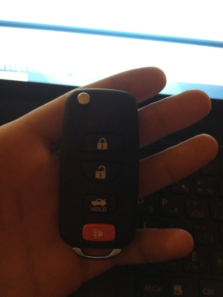
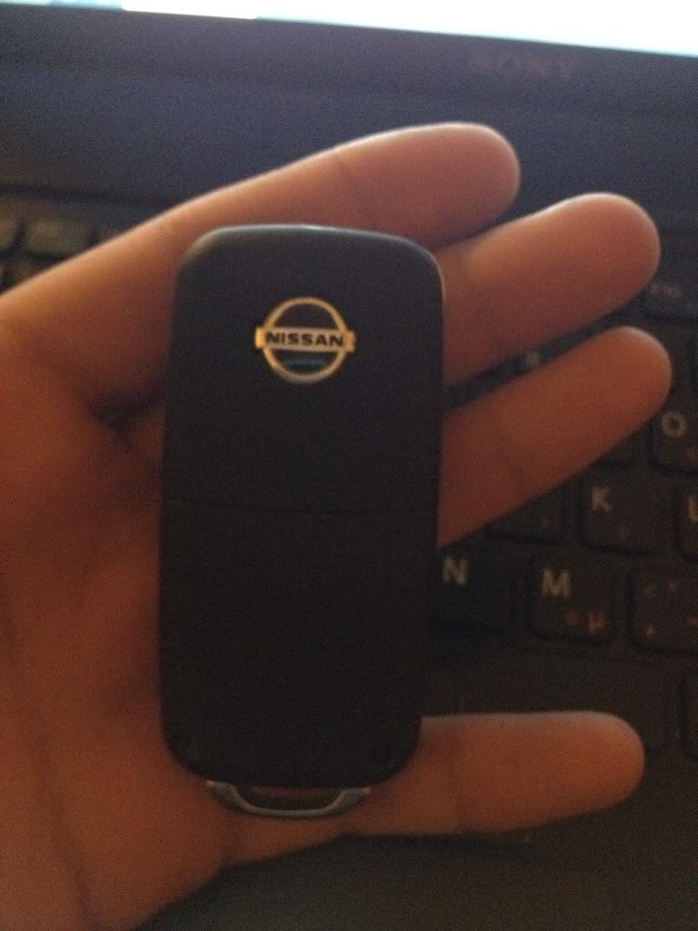
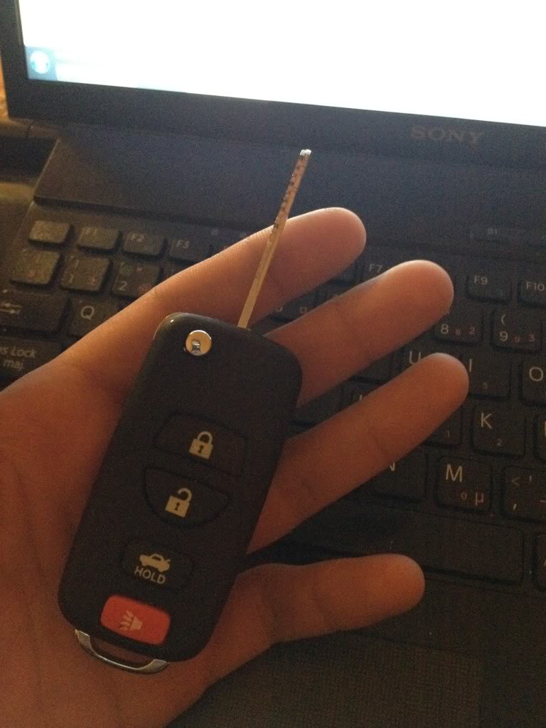
comes with full fob (some have case only), uncut blade & chip


Registered User
Joined: Nov 2011
Posts: 558
Likes: 28
From: Wilmington
A solder gun is like $10 at pepboys, Double sided tape, and a dremel, I got one from habor freight for $7.
you only need to solder the battery piece. The wires can stay in under tension.

Yeah, I know they tools to make it aren't all that expensive, just as I said before.. lack of patience is what's stopping me at this point.

Registered User
Joined: Nov 2011
Posts: 558
Likes: 28
From: Wilmington

Registered User
Joined: Nov 2011
Posts: 558
Likes: 28
From: Wilmington

if so you can use it but you lose the truck feature. This remote is for the FX.
You really want this
